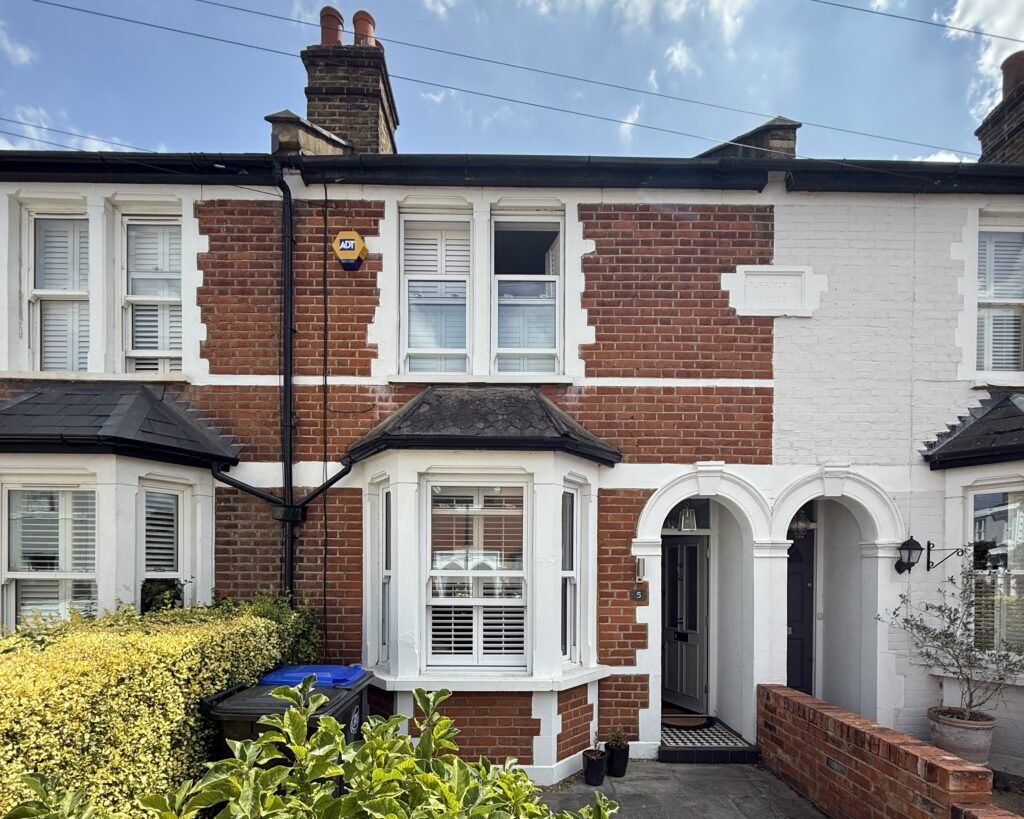
Ells, an architect we work with regularly, got in touch about a small Victorian cottage in Molesey.
The brief was the usual package they ask from us:
- Full measured survey of the cottage
- Existing floor plans, elevations and one section
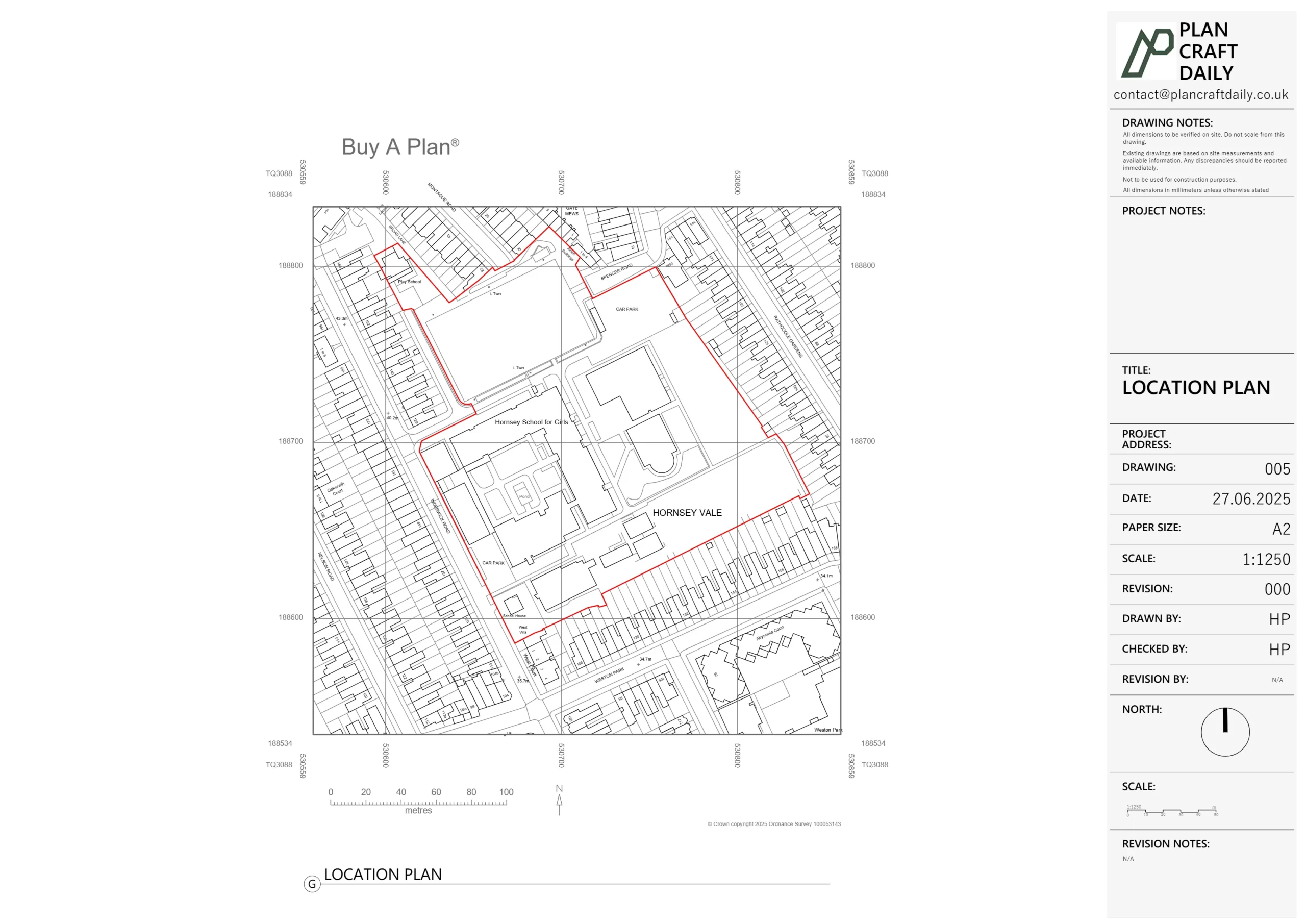
- Manholes and boundaries mapped clearly for planning
- Drawings suitable for a domestic planning application
At the time, we were already running at full capacity and in the process of expanding our CAD team. We were upfront about that:
- We explained we couldn’t take anything new on until mid-July,
- Then offered dates after 12–14 July as realistic survey slots,
- So Ells could manage expectations with their client from the start.
Despite the busy period, they specifically wanted to keep this project with us, so we agreed to add it to the diary as soon as capacity opened up.
Scheduling the survey – aligning diaries around a single preferred slot
Once the quote for 5 Park Road, Molesey was agreed, the next challenge was timing.
- Ells asked if we could do Friday 18th July, AM, as that was the client’s preferred slot for that week.
- We reshuffled what we could and confirmed we could attend on Friday 18th with an arrival window of 11:00–11:30am.
We then:
- Issued the initial invoice, explaining that payment would secure and activate the survey slot.
- Received confirmation and issued a payment receipt along with:
- Surveyor name: Mustafa Bashkal
- Arrival time window
- Ells shared the on-site contact details for the homeowner (Pete) and asked that Mustafa text when he was on the way with an ETA, which we built into the surveyor’s schedule.
That meant everyone knew:
- Exactly when we were attending,
- Who would be on site, and
- How communication would work on the day.
How we carried out the survey – cottage, drainage and boundaries
On the Friday, Mustafa attended and carried out a full measured survey of the cottage and its external context.
On site, he captured:
- Internal geometry
- Room sizes, wall thicknesses and openings using a laser distance meter and manual checks
- Floor-to-ceiling heights, stair pitches and landings
- Structural clues (nibs, chimney breast projections, thicker walls) that matter for later design/engineering
- External envelope & elevations
- Front and rear geometry, window/door positions and sill/head levels
- Roof forms, eaves lines and chimneys
- Key features that define the Victorian character, as these often matter to planners
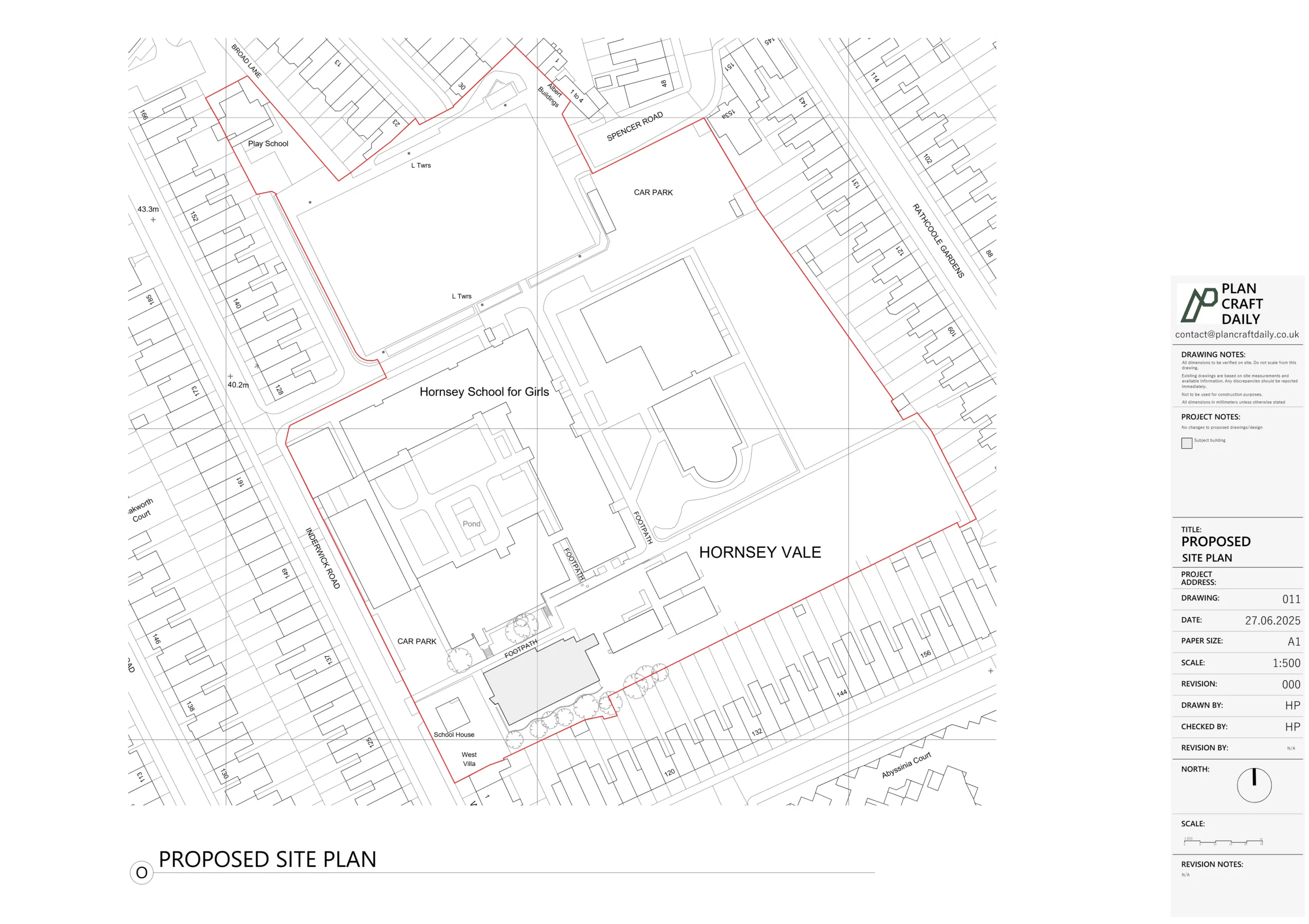
- Manholes and boundaries
- Manhole positions and cover types
- Fence lines, walls and boundary markers, measured back to fixed building points
- Enough information to produce a readable boundary line and drainage diagram on the drawings
- Photo record
- Systematic internal and external photos to support remote design and future checking
- Context shots of boundaries, corners and junctions that often cause questions later
Back in the office, survey data and photographs were logged against the Trello card and pushed into our CAD workflow.
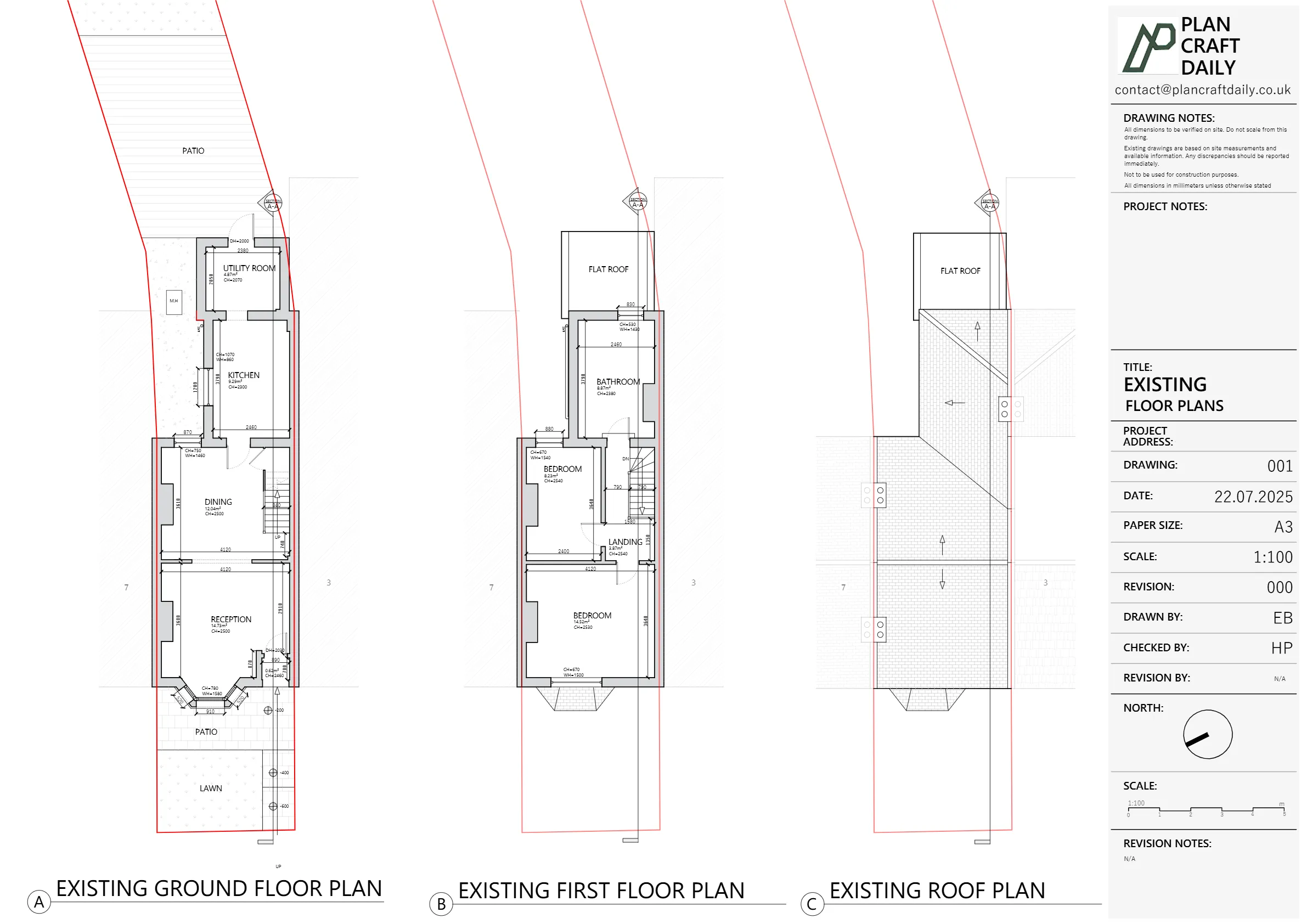
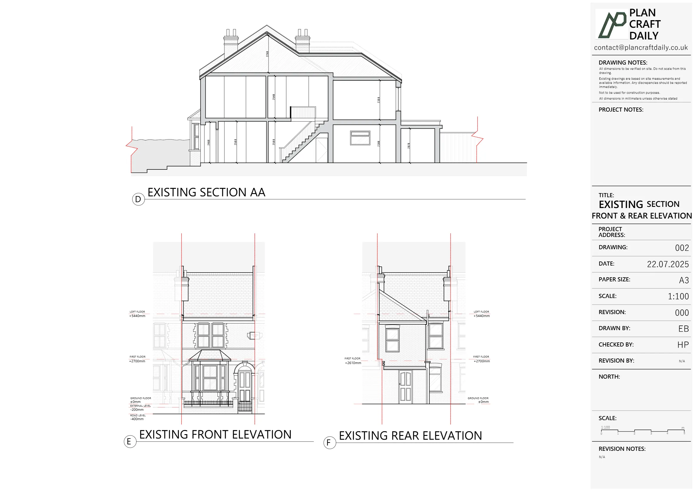
Turning the survey into drawings – first issue
Within the agreed timeframe, our CAD team produced a draft drawing pack, including:
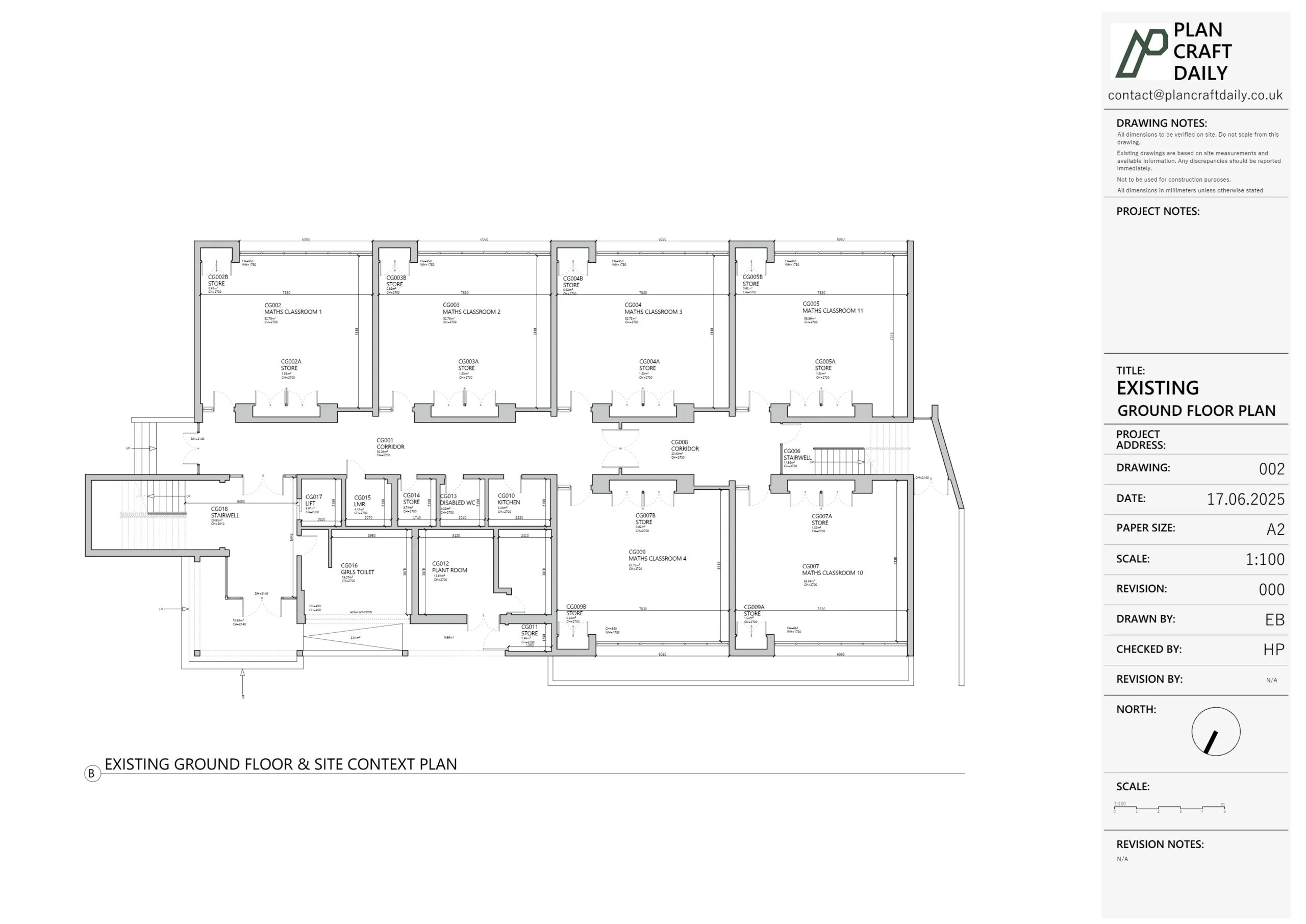
- Existing floor plans
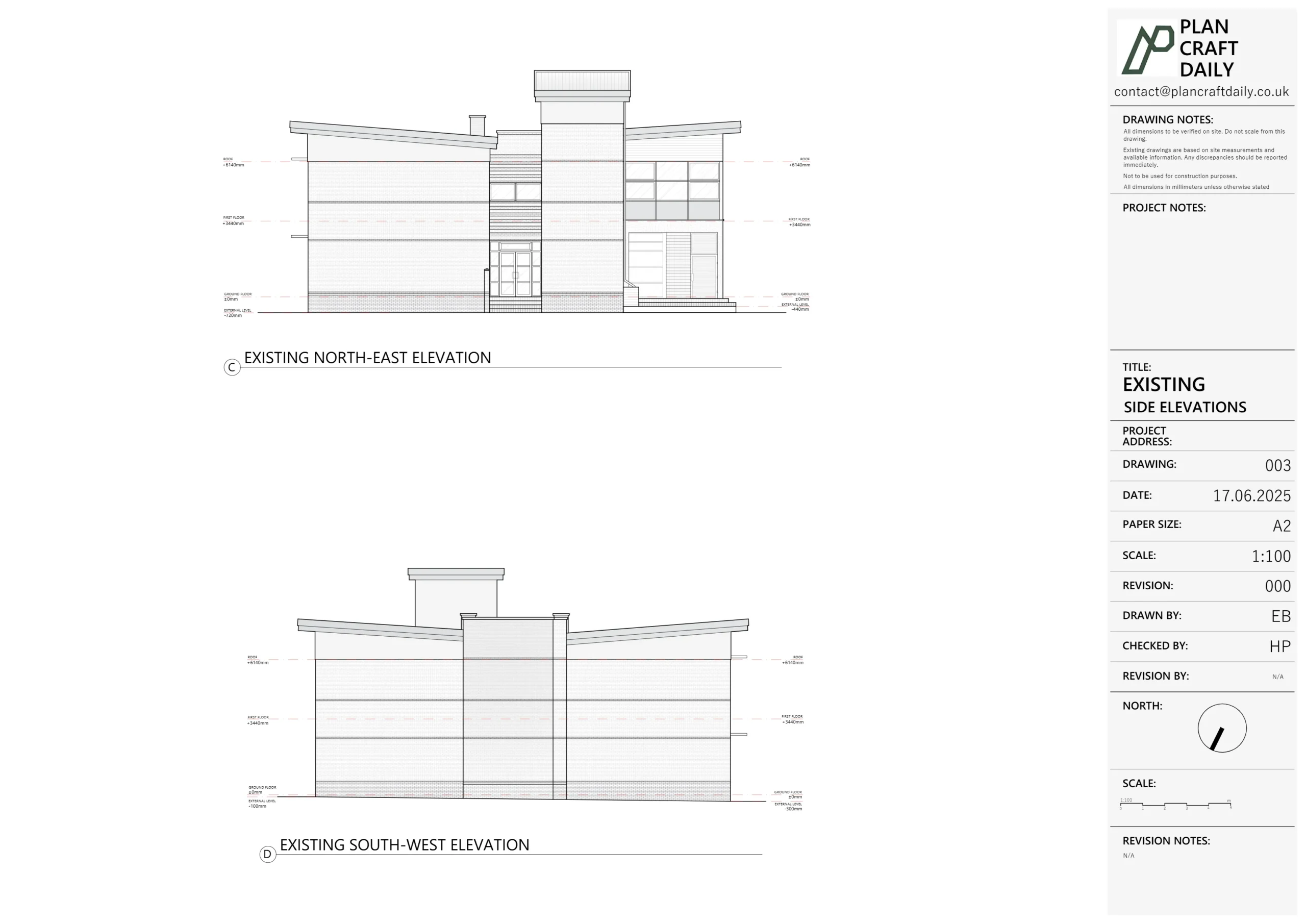
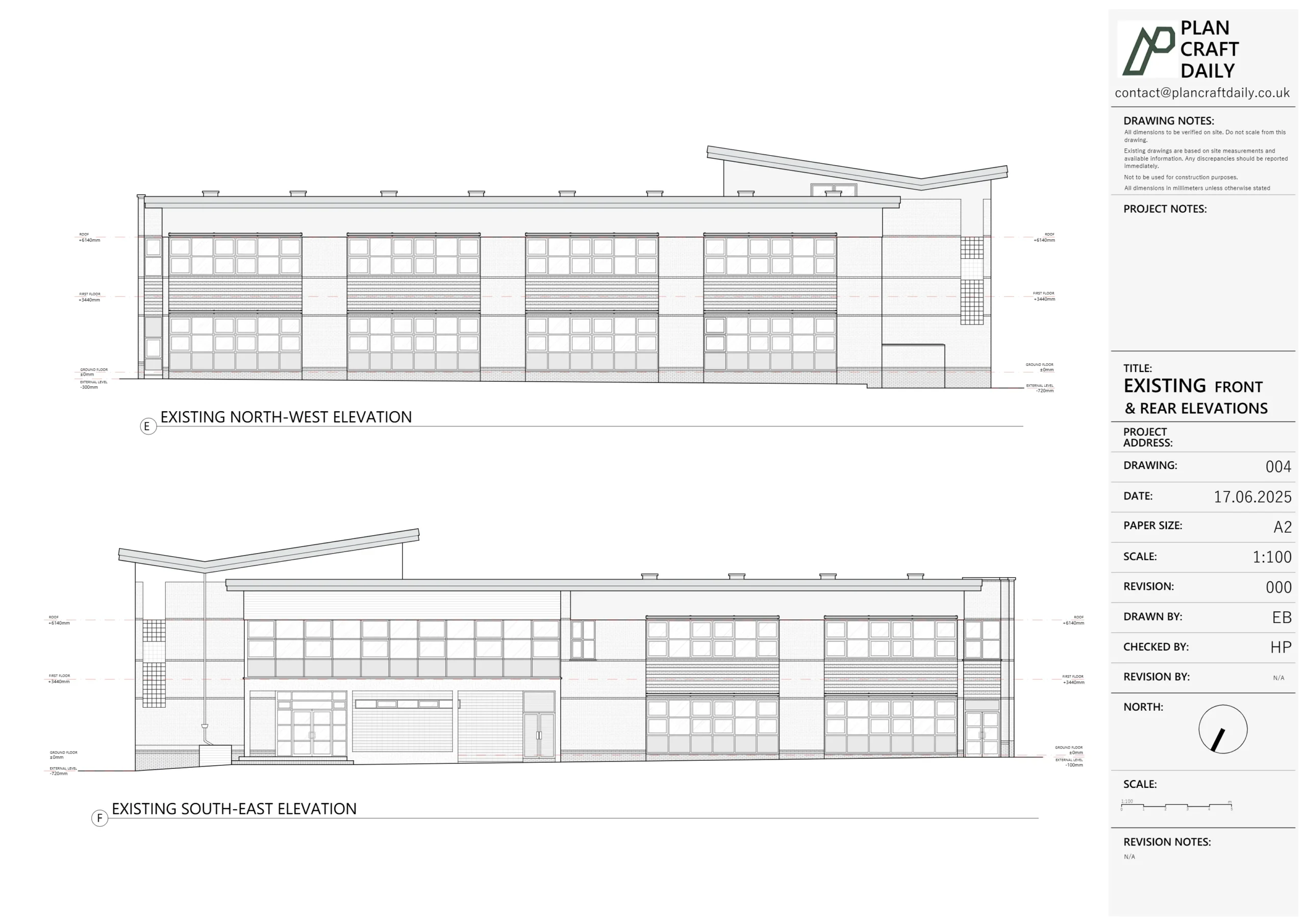
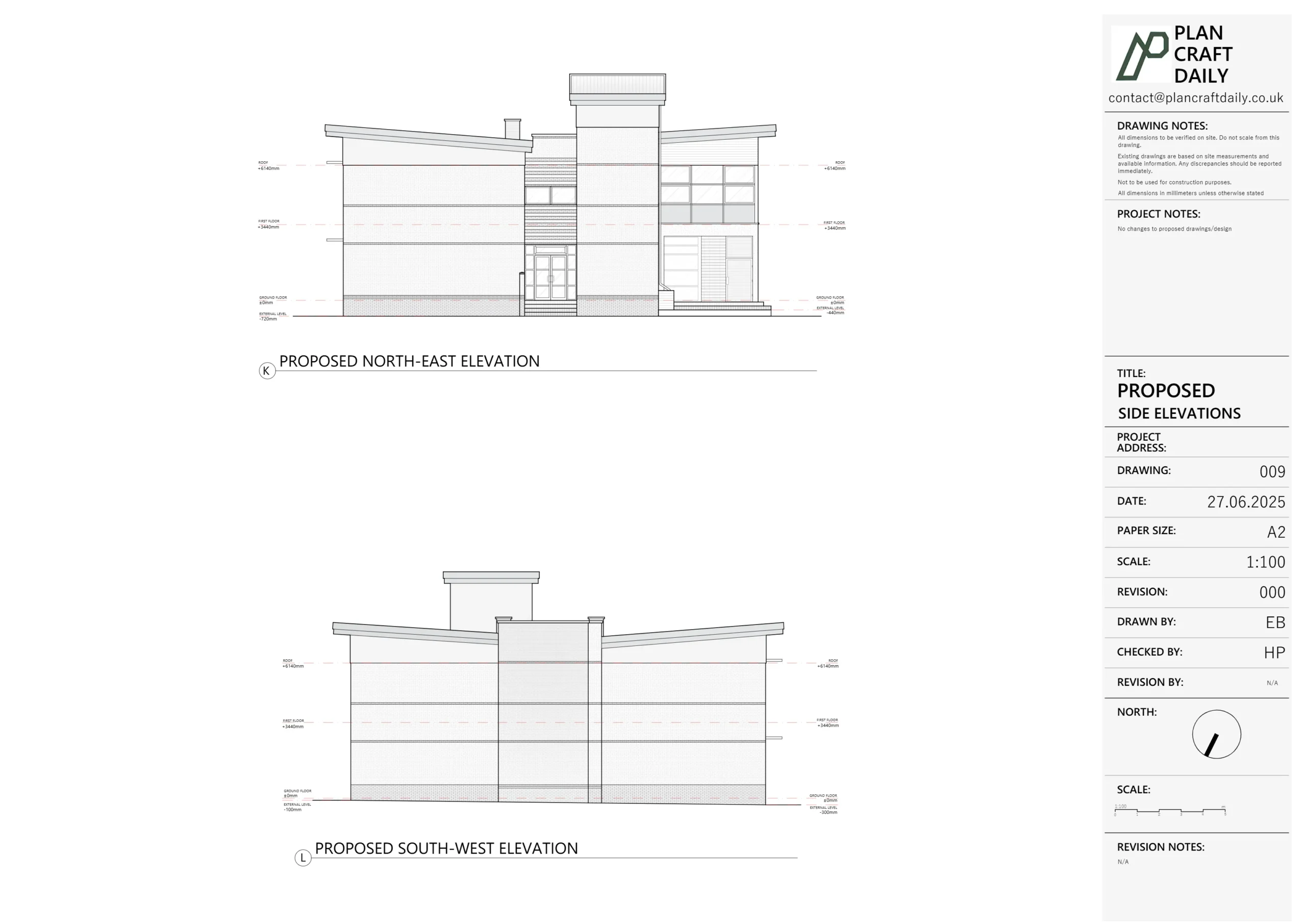
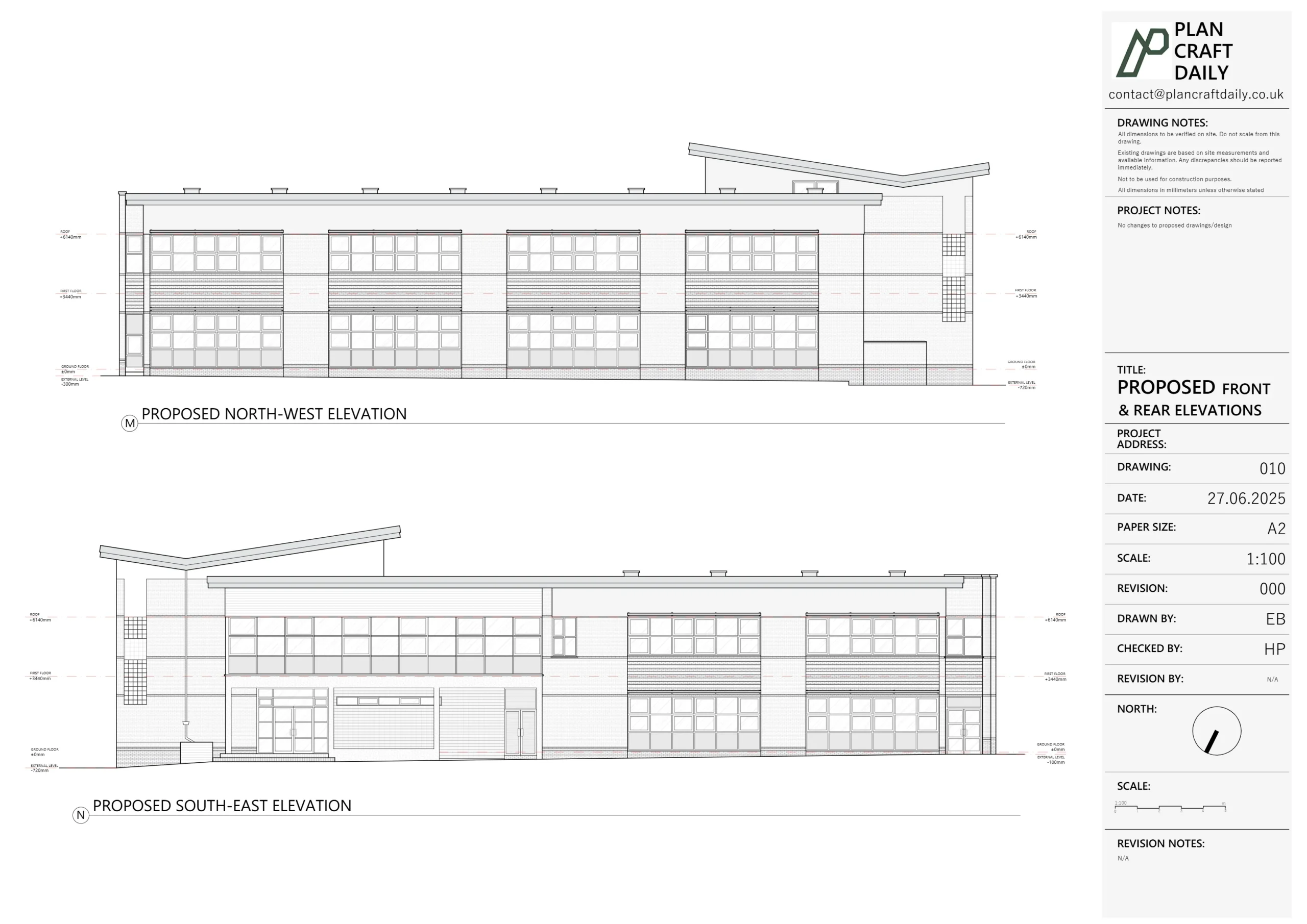
- Front and rear elevations
- A section through the most relevant part of the cottage
- Manholes and boundaries mapped on plan
We:
- Ran the drawings through our internal QA
- Issued a draft ZIP pack to Ells for review
- Attached the final invoice, with the standard wording that once the payment was settled we’d issue:
- Final CAD (DWG),
- Final PDFs,
- Supporting photographs.
Ells reviewed the draft and then came back with a planning-specific request.
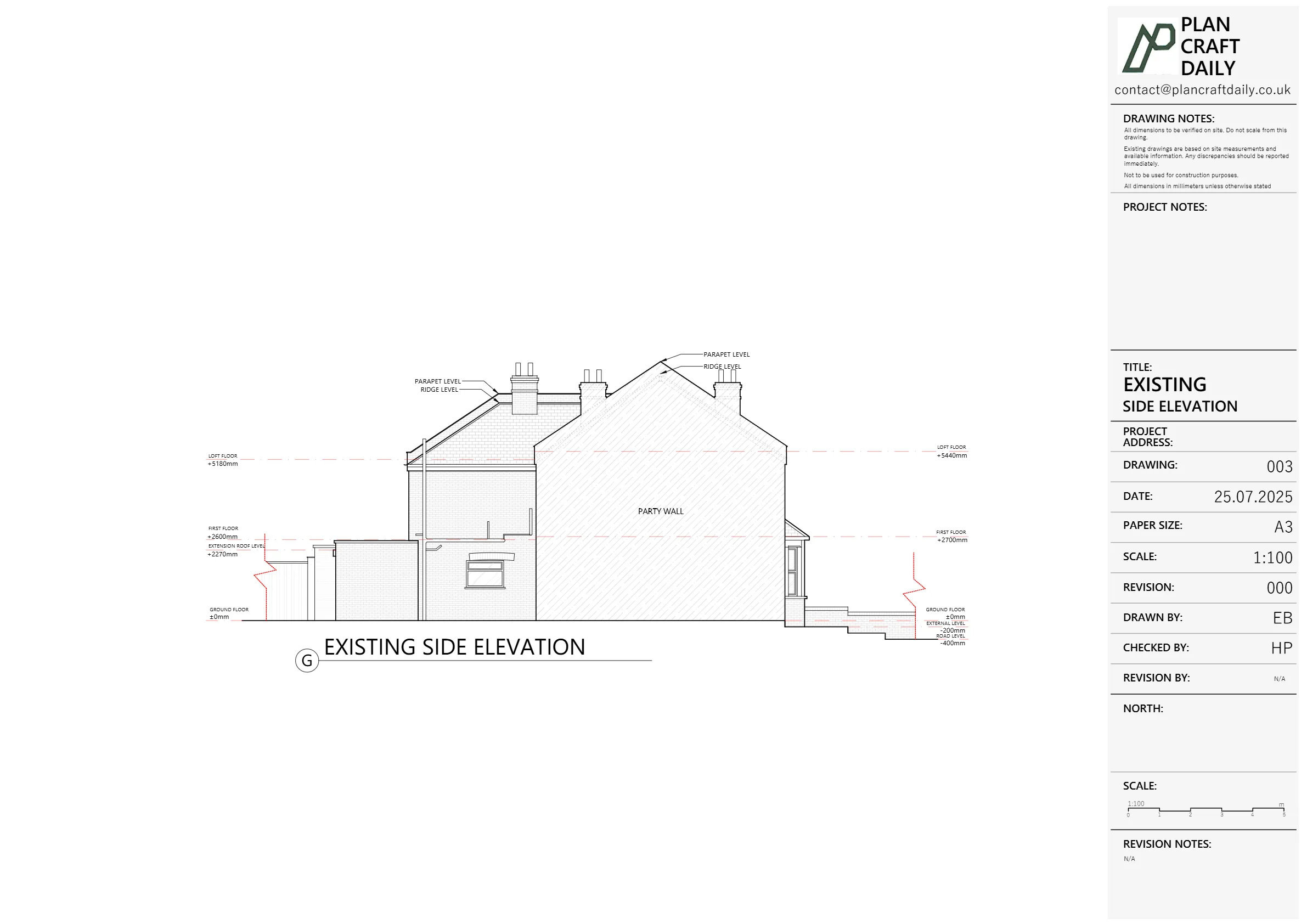
Managing changes – adding a side elevation for planning
Ells realised that for their planning application, they would need at least one side elevation, ideally looking in the opposite direction to the section we’d already provided.
We assessed the extra work required and replied:
- Confirming that we could produce the side elevation,
- But that it was outside the original scope,
- So there would be a small extra charge (handled via a revised quotation and final invoice).
Once Ells agreed:
- We revised the quotation and invoice to include the extra elevation.
- Our CAD team prepared the additional side elevation, ensuring:
- It lined up exactly with the existing section,
- Window and door positions matched both the survey and the photos,
- The elevation read cleanly for planning purposes (no unnecessary detail, clear levels).
We then issued a revised draft pack containing the updated sheets plus the new side elevation, alongside the updated invoice.
When Ells confirmed everything looked good and made payment, we:
- Issued the payment receipt, and
- Released the final drawings and related files (CAD, PDFs, photos), moving the project to Completed.
Boundary query after completion – using hand mark-ups to support design
A little while later, after their own site visit and further photo checks, Ells noticed that the shown boundary positions didn’t quite match what they were seeing on site or in their photographs.
Instead of simply flagging it as “wrong”, they asked a very sensible question:
“Please can I get the hand mark-up for this one? The boundaries aren’t quite working in terms of their shown position vs photos and my site visit. Just want to see what was measured so I can resolve.”
This is exactly why we keep clear, structured field notes.
Our response:
- We retrieved the original survey sketches and dimension chains for the boundaries.
- Harry prepared a hand-marked overlay (Survey_Drawing.png), showing:
- Which lines had been physically measured on site,
- The key dimensions from built corners to fence lines/walls,
- How the boundary had been interpreted for the CAD drawing.
We then sent Ells:
- The hand markup as a clear reference,
- With a short note explaining that this should help resolve the discrepancy between their photos, their site impression and the drawing.
In other words, we didn’t just say “the drawing is correct”; we gave them the raw survey logic so they could reconcile everything on their side (and, if needed, refine the boundary line based on later legal or title information).
Final outcome – a flexible survey partner for planning-led cottage projects
By the end of the Park Road project, Ells and their client had:
- A complete existing-conditions drawing pack for a small Victorian cottage:
- Plans, elevations, a section, manholes and boundaries
- An extra side elevation tailored to planning requirements, agreed and priced transparently as a variation
- Final CAD, PDFs and photos ready for planning, design development and tender
- A hand-marked boundary sketch that made it easier to line up survey data with on-site reality and photographs
For us, this project highlights a few things we see often on smaller residential jobs:
- Capacity constraints can be managed as long as we’re upfront about dates.
- Architects sometimes need small but critical scope changes (like an extra elevation) – we handle those quickly and clearly.
- Boundaries and drainage frequently raise questions later; having good field notes and being willing to share them makes life easier for everyone.
If you’re working on a similar small-house project – especially where accurate boundaries, manholes and planning-ready elevations matter – our role is to give you a survey and drawing pack that you can trust, and to be on hand afterwards if you need to dig into the details.
Project Details
| Service Type | Measured survey, existing plans & elevations, section, manholes and boundary mapping |
| Time Taken | 2 weeks |
| Budget | £500–£650 |
| Location | Molesey, Surrey |