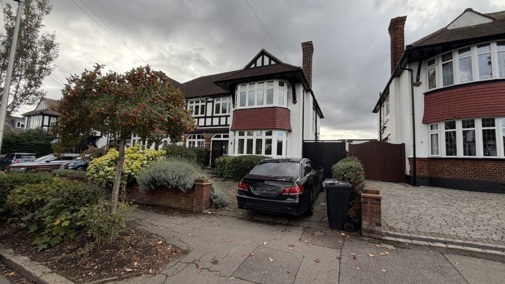
James, an architect we’ve worked with before, got in touch about a semi-detached property in Woodford Green. He wanted a clean, reliable set of existing drawings to support design work and potential planning for the house.
His brief was very clear and technical:
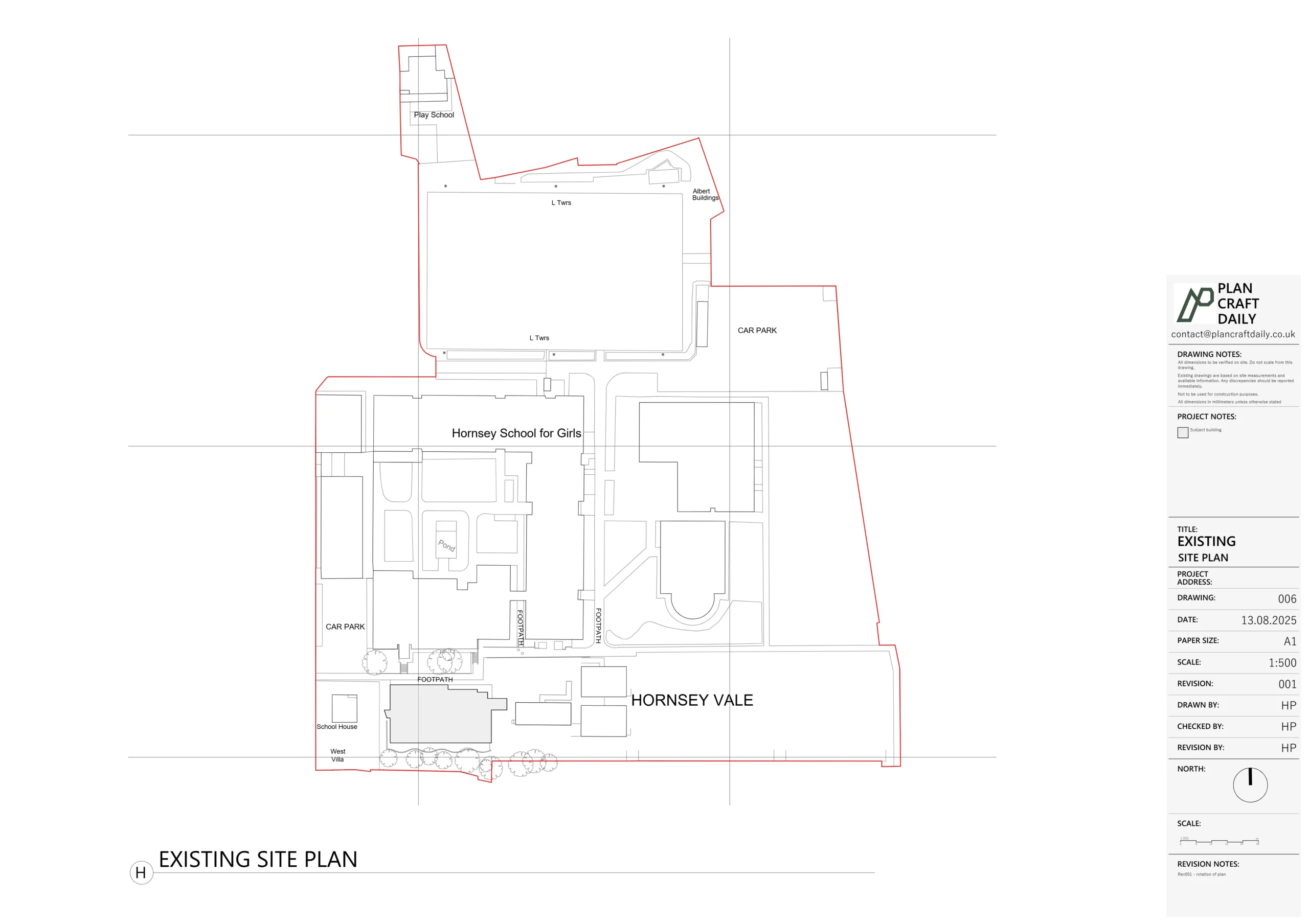
- Ground floor plan, including standard boundary positions and indication of neighbouring buildings (similar to a previous project we’d done together on Hillcrest).
- First floor plan.
- Three elevations (to suit the semi-detached form).
- An outline section showing:
- Floor-to-ceiling heights
- Floor thicknesses
- Roof angle
- Rafter thicknesses
He also confirmed that the outbuilding/garage was not required this time, which helped keep the scope tightly focused on the main house.
Scoping the brief and securing the survey date
After receiving the email request, we:
- Prepared a detailed quotation clearly listing each drawing (plans, 3 elevations, outline section) and confirming DWG deliverables.
- Asked a single clarification question—whether the outbuilding should be included—to avoid any assumptions.
- Proposed a survey date of Tuesday 21st October, with an arrival window between 1:00 pm and 2:00 pm.
James confirmed:
- He was happy with the quotation.
- The garage/outbuilding could be excluded from the survey.
- He wanted to book in the Tuesday slot.
We then:
- Issued the initial invoice.
- Received payment confirmation from James.
- Sent a payment receipt and the survey details, including:
- Surveyor: Ali Uddin
- Arrival window: 1:00–2:00 pm
- Contact number, so James knew exactly who was attending on the day.
How we carried out the survey
On the agreed date, Ali attended within the agreed window and carried out a full internal and external measured survey of the main house.
Equipment & approach included:
- A disto laser for quick, accurate internal dimensions to both floors.
- Traditional tape checks on key diagonals, stair runs and tricky corners to validate the laser data.
- Careful recording of:
- Wall thicknesses and structural vs non-structural partitions.
- Stair geometry and headroom for the outline section.
- Floor build-ups (via floor level changes and ceiling references) to back-calculate floor thicknesses.
- External measurements to support:
- Three elevations (front, rear, and exposed side for the semi-detached form).
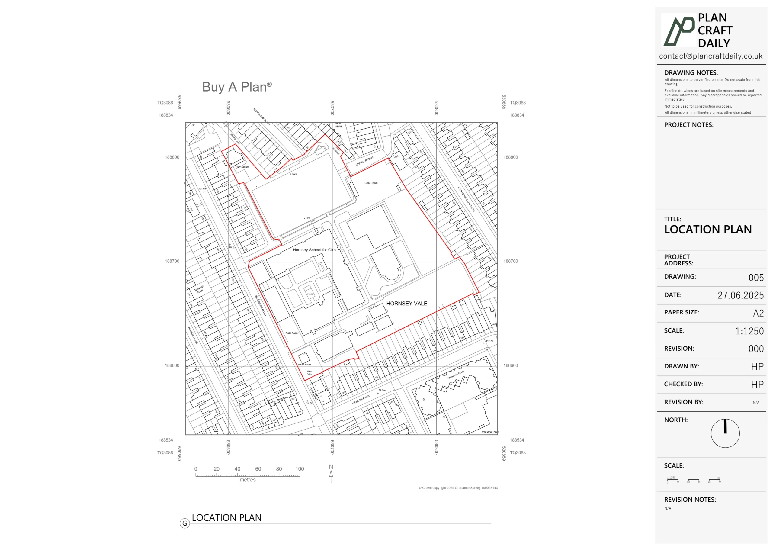
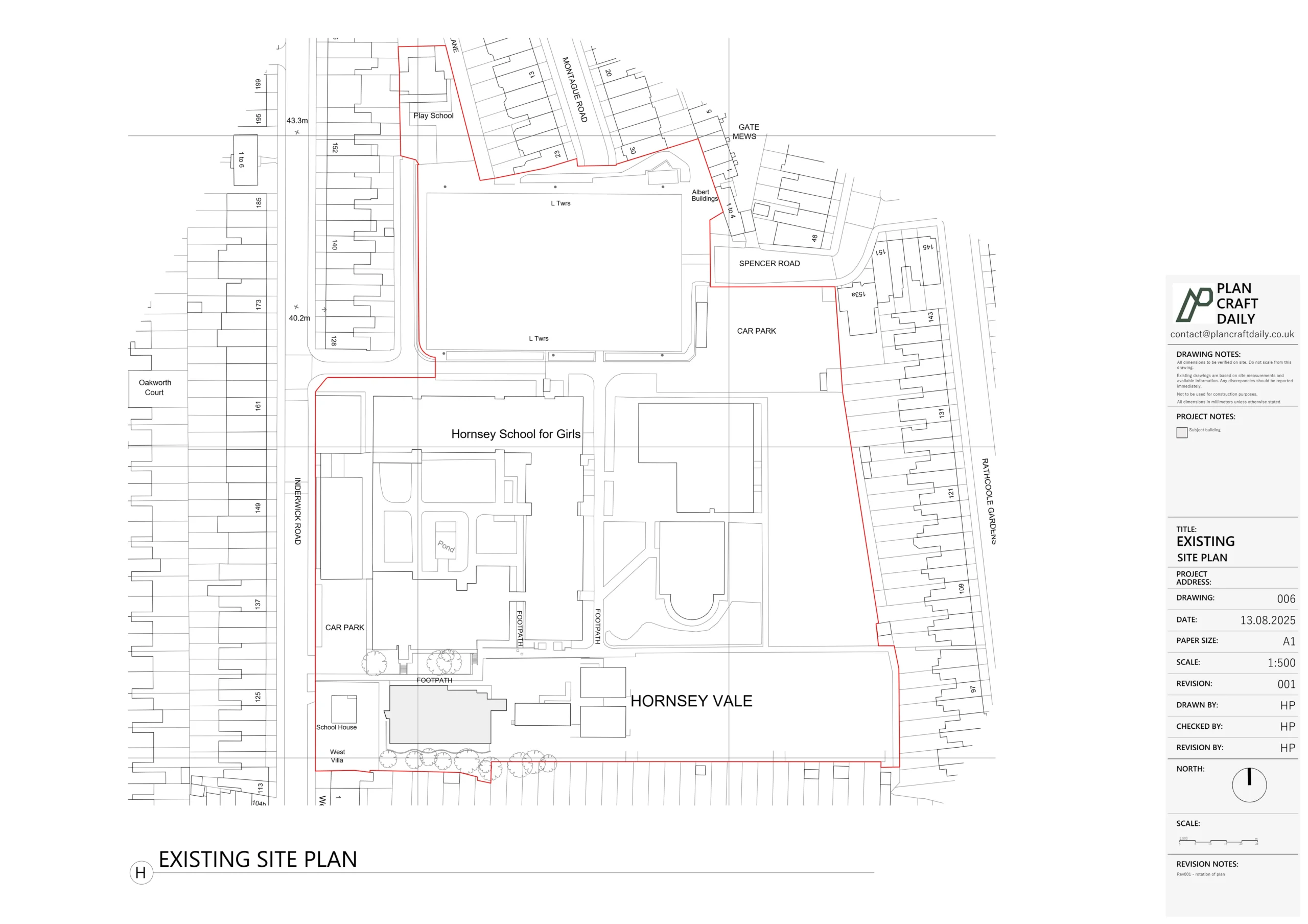
- Context of neighbouring buildings and standard boundary positions, as James had requested “similar to Hillcrest”.
The focus for this project was less about the garden and outbuildings and more about giving James a precise internal shell and external envelope so he could confidently develop extension and reconfiguration options.
Turning the survey into drawings
Back in the office, our CAD team translated the raw measurements into a structured AutoCAD model:
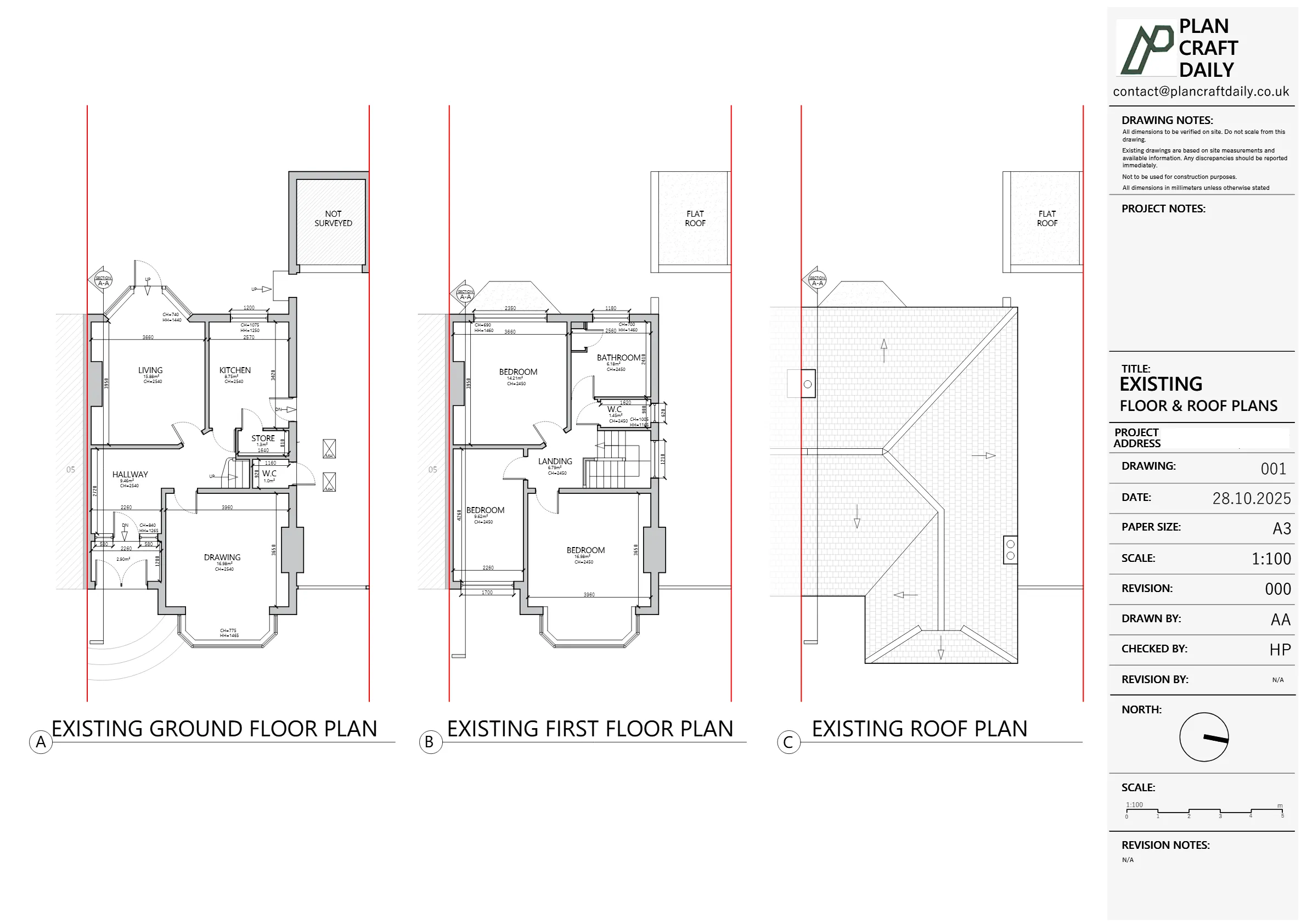
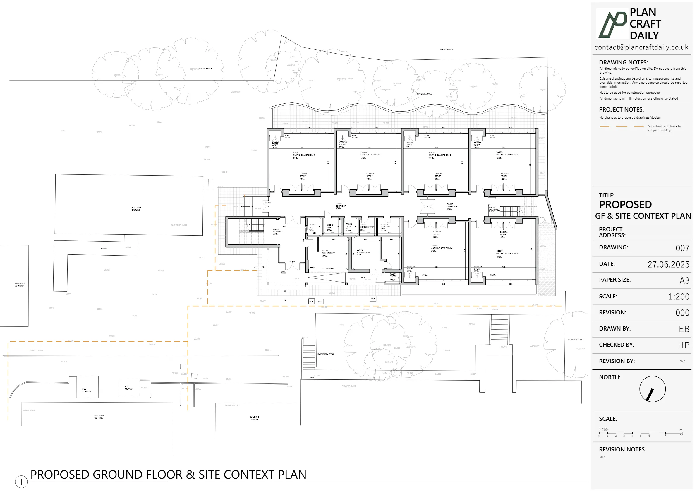
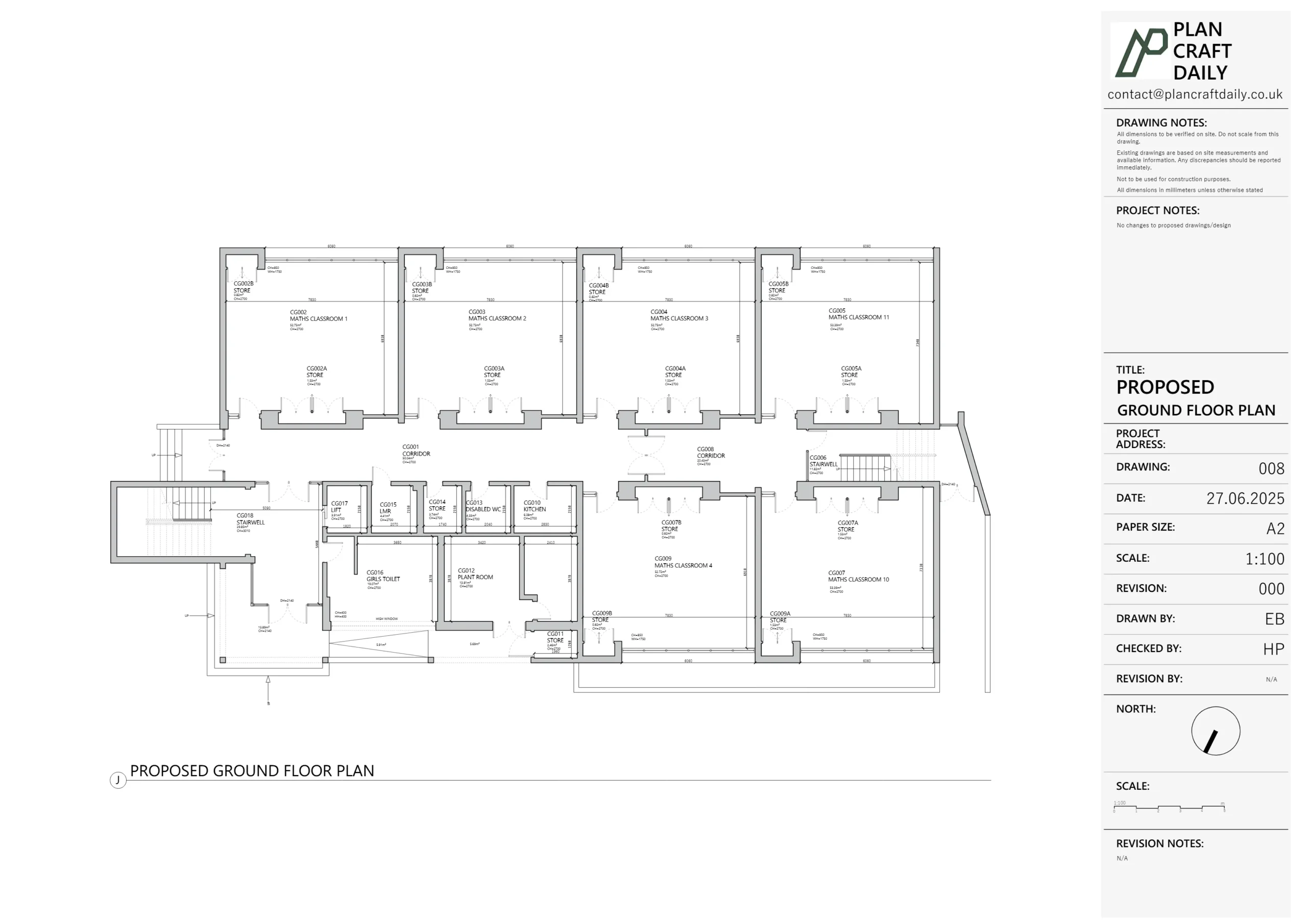
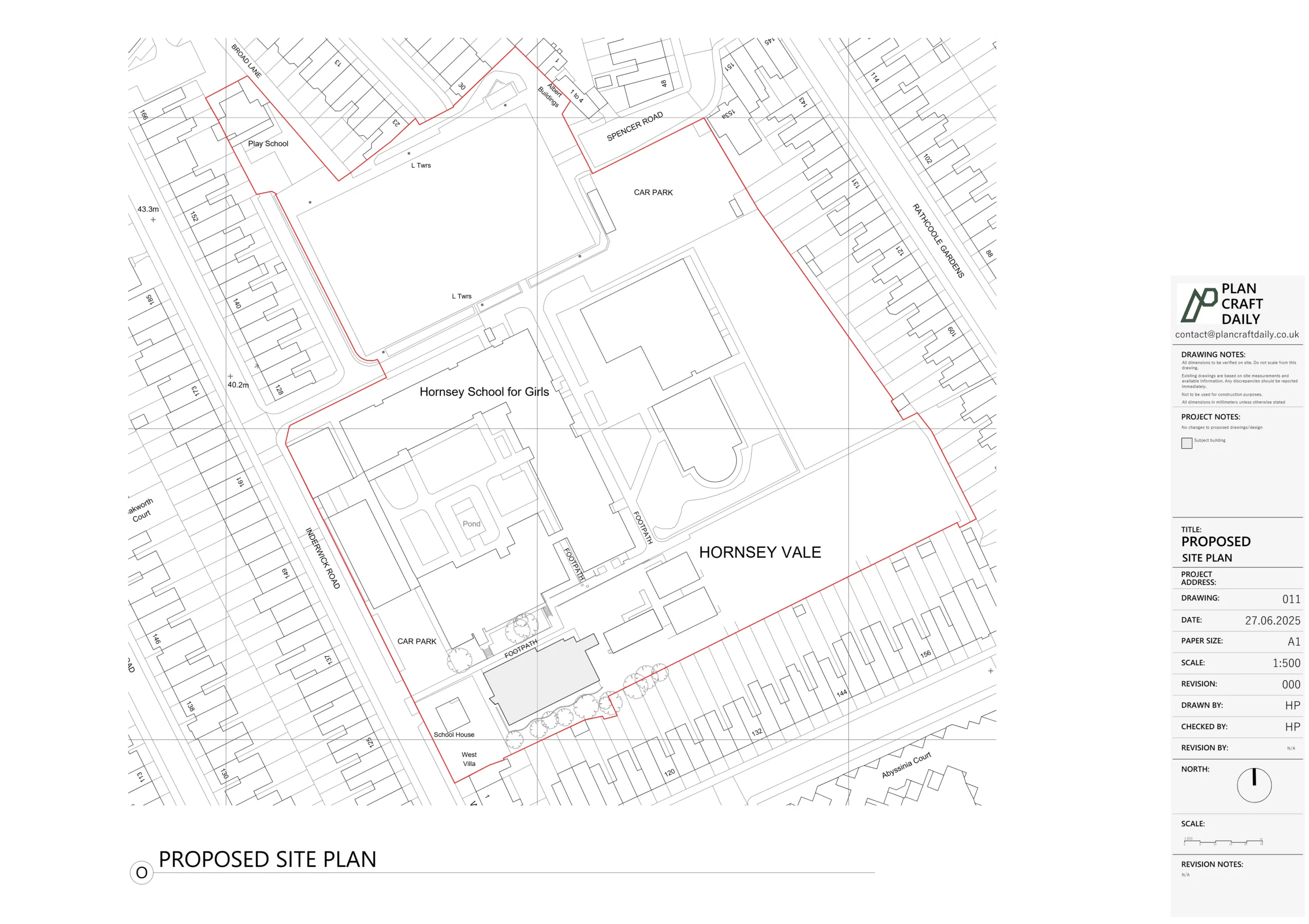
- Existing ground floor plan with:
- Main walls, openings, and key internal features.
- Boundary line and simple neighbour massing for context.
- Existing first floor plan showing:
- Room layout, window/door positions, and stair connection back to ground floor.
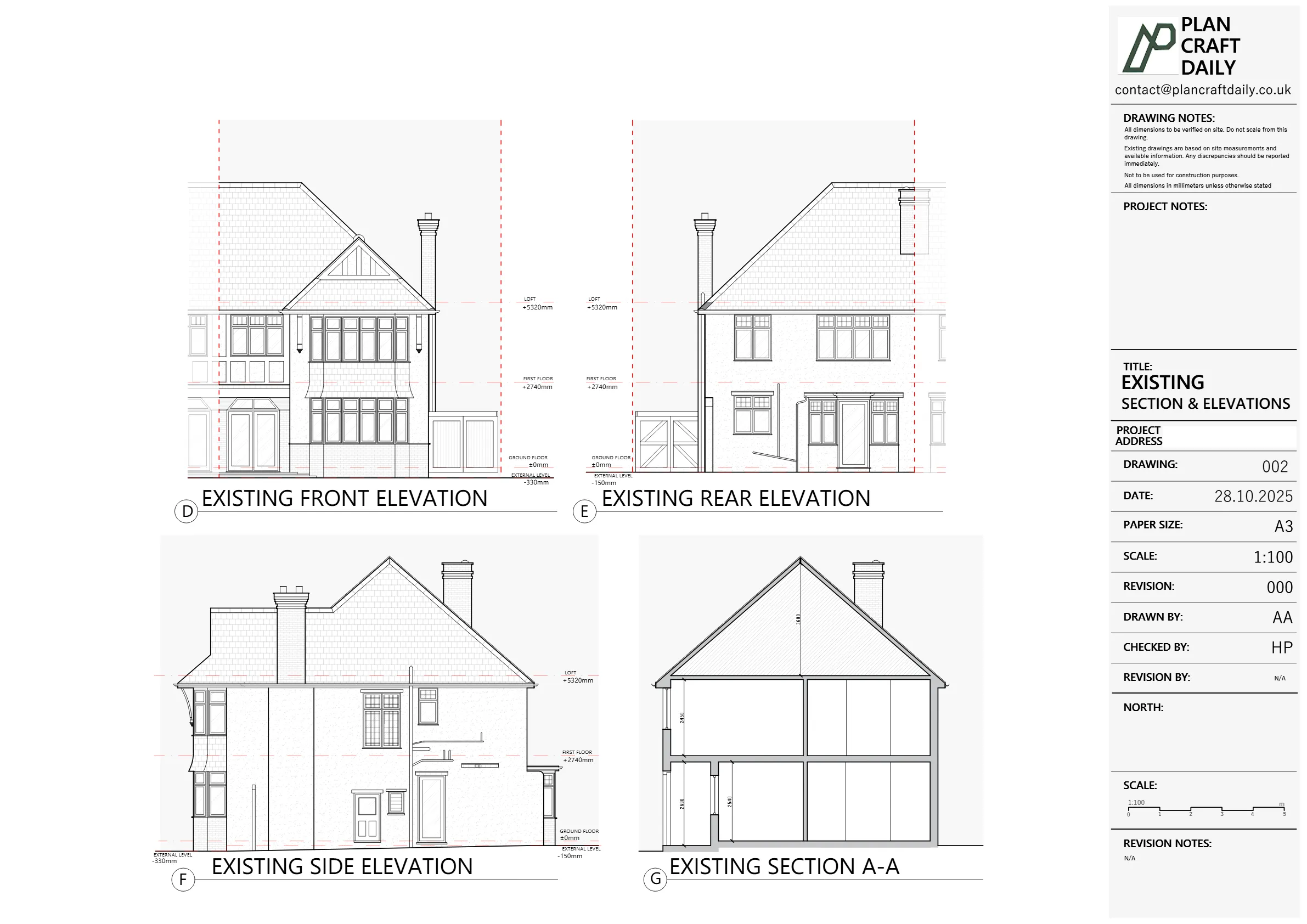
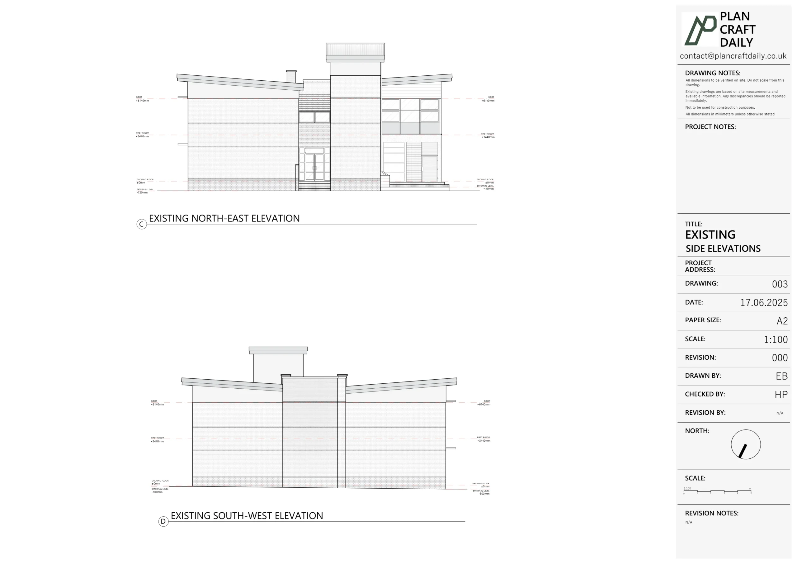
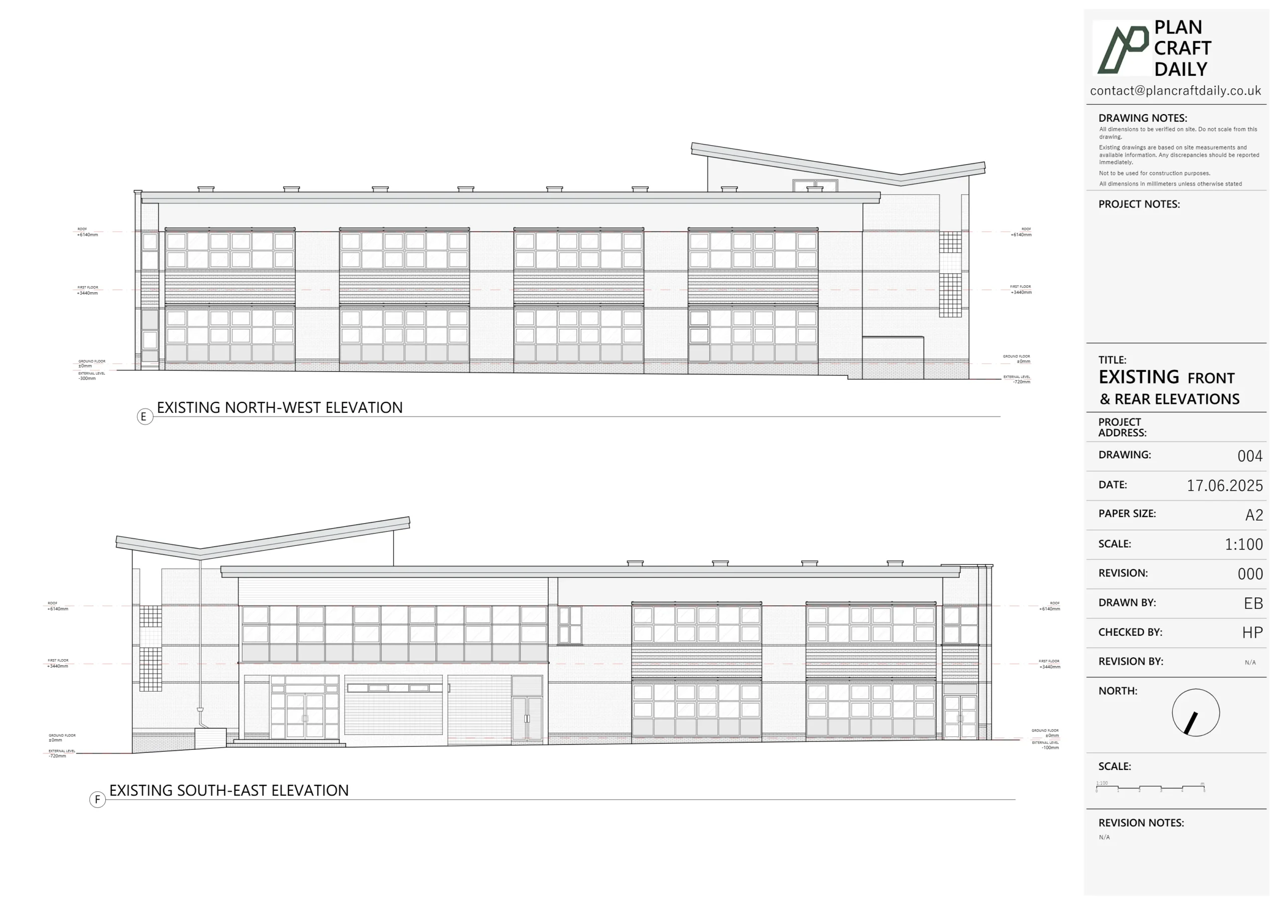
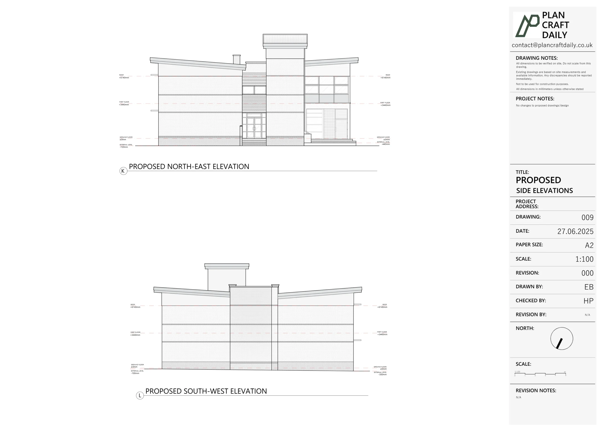
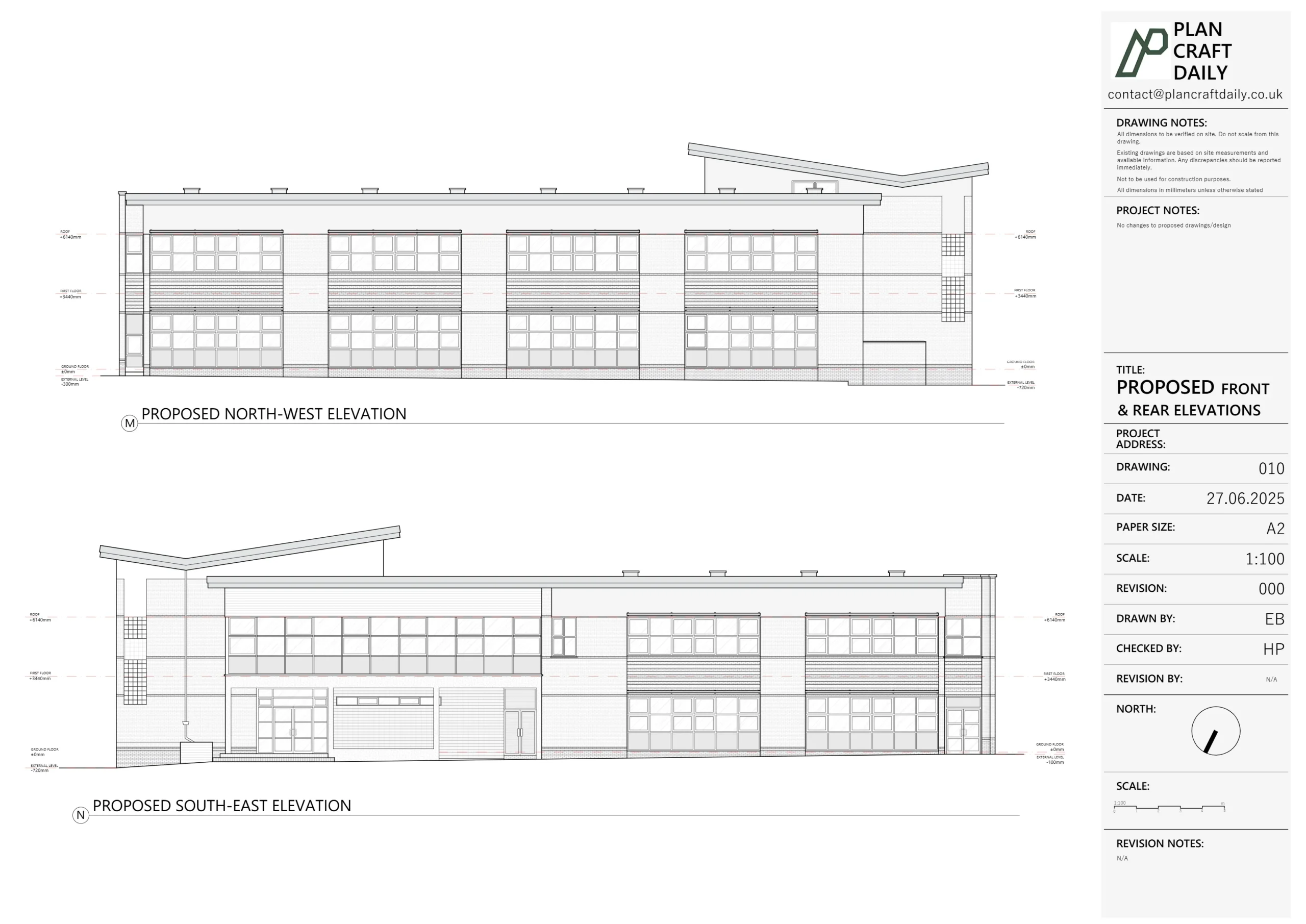
- Three elevations:
- Front elevation, rear elevation, and the exposed side elevation, each tied correctly to shared levels.
- A small level of neighbour context where helpful, to make planning visuals and design sections clearer.
- Outline section:
- Floor-to-ceiling heights for each storey.
- Approximate floor thicknesses based on surveyed level differences.
- Roof pitch and rafter depth, tying back to measured soffit, ridge, and internal ceiling lines.
We used our usual UK-standard layering and naming conventions, so the DWG file would drop straight into James’s workflow without relayering.
All drawings then went through our internal QA check, where we cross-verified:
- Plans vs elevations (window/door positions, sill/head levels).
- Levels and dimensions across the section vs the plans.
- That the building line and neighbour massing matched the on-site notes and James’s expectations.
Managing communication & finalising the pack
Internally, once the survey was complete, we moved this project from Confirmed to In Progress, and then to Approval / Finalisation once the CAD work was ready.
We then:
- Exported a draft PDF pack for James titled as the project address (without sharing full address publicly in the case study).
- Attached the final invoice with a clear explanation that:
- Once the balance was settled,
- We would provide the final drawings, including the CAD file, PDFs, and photographs from the survey.
As with our other projects for James, the communication was concise and to the point: he had everything he needed to review, sign off, and get the DWG into his design pipeline quickly.
Final outcome
For this Woodford Green semi-detached property, James received:
- A clean, accurate existing drawing set tailored exactly to his brief (plans, three elevations, outline section).
- A DWG file structured for immediate use in his own CAD environment.
- PDFs ready for quick client discussions, design markups, and early-stage planning conversations.
From first enquiry to draft issue took roughly a week after the survey date, with a clear, single point of contact throughout.
For us, this project was another example of how we work with returning architect clients:
tight scope, reliable measurements, and drawings that make the design phase smoother instead of getting in the way.
Project Details
| Service Type | Measured survey + existing drawings (GF plan, FF plan, 3 elevations, outline section) |
| Time Taken | Around 1–2 weeks |
| Location | Woodford Green |