Ells, an architect we work with regularly, approached us for two new residential projects at the same time:
- Leaf Close – a two-storey end-terrace property needing a full internal reconfiguration.
- Strathville Road – a ground-floor maisonette with a planned single-storey wrap-around extension.
This case study focuses on Leaf Close, where the key brief was:
- A full measured survey of the existing house.
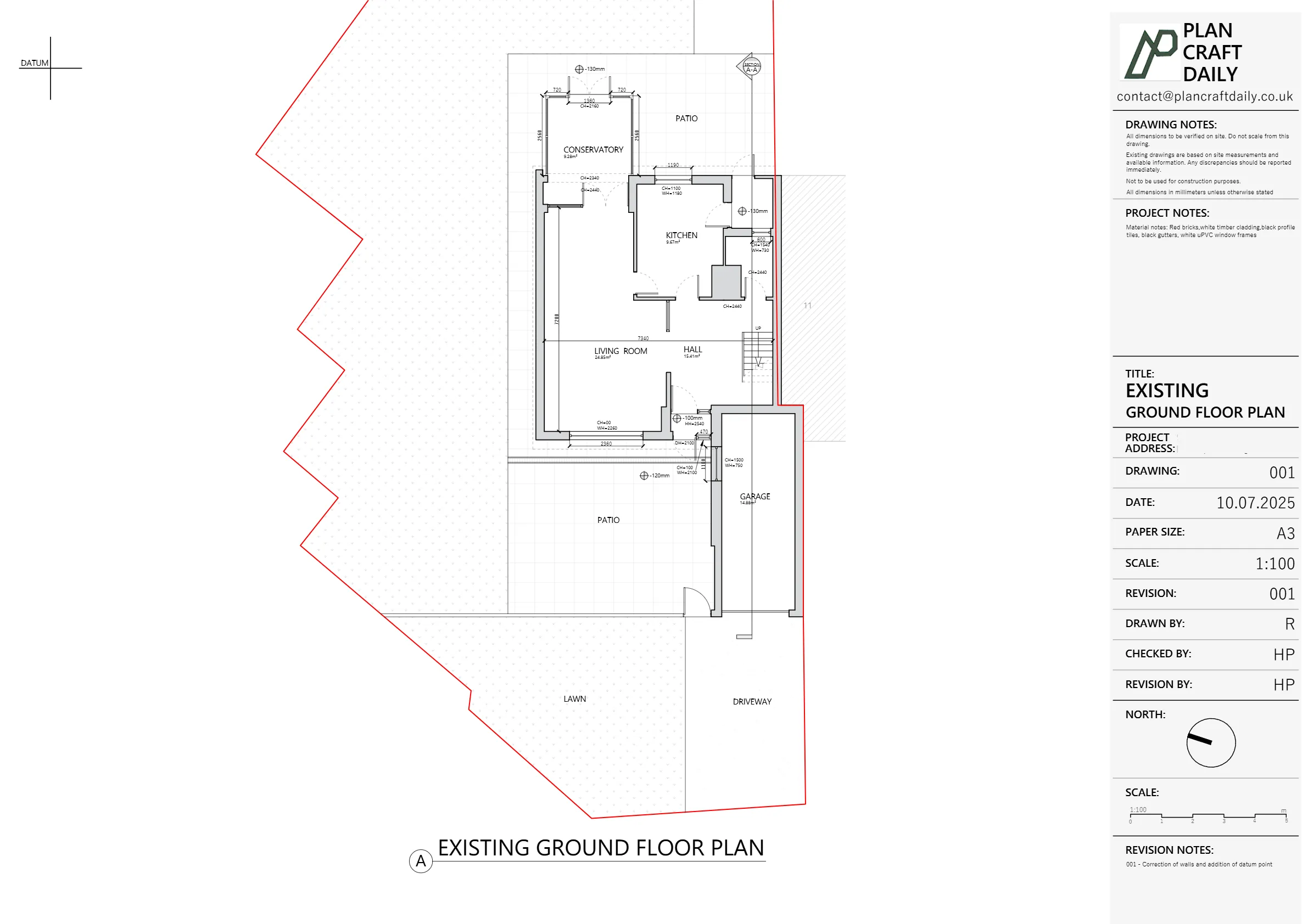
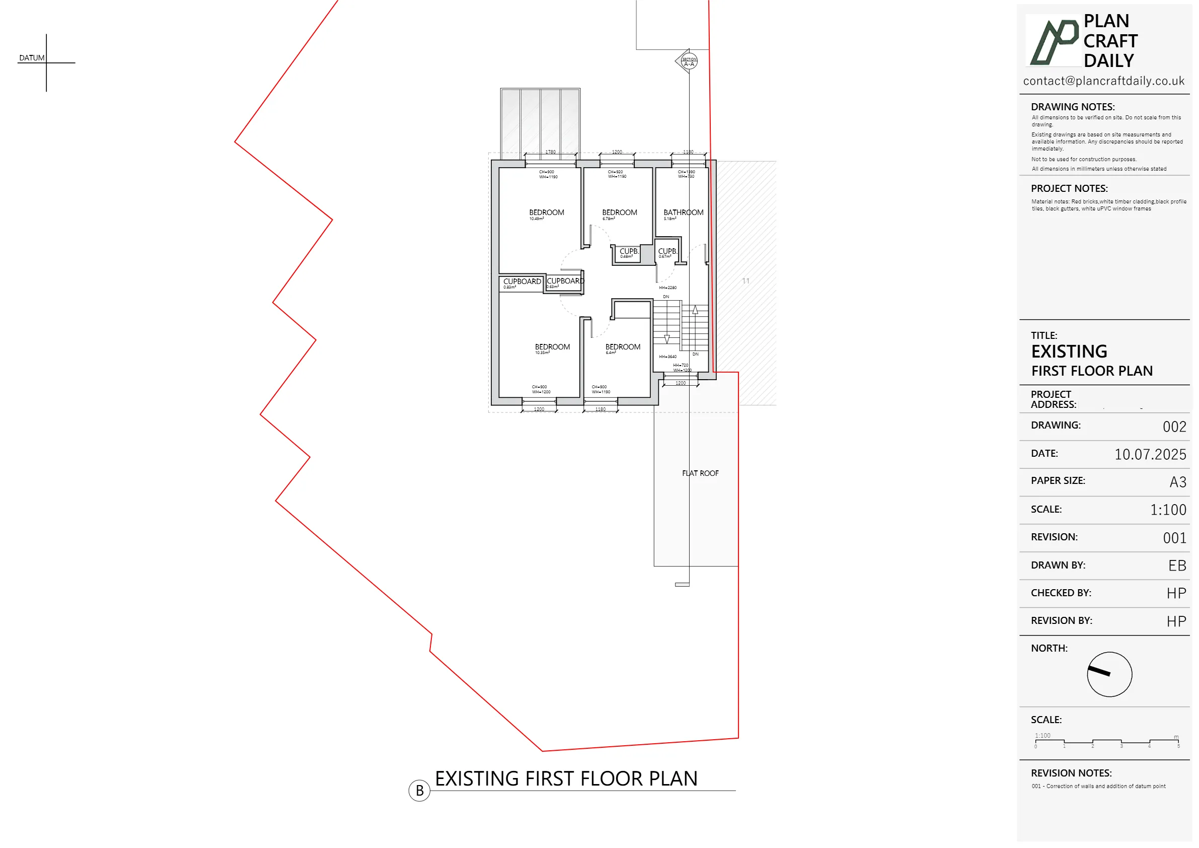
- Existing plans, elevations and one section suitable for options on re-planning the ground and first floors.
- Enough accuracy for Ells to make safe decisions on which walls might be load-bearing before advising their client on removing or reducing wall lengths.
Because the two projects were instructed together, we produced a paired quote and coordinated survey dates so Ells could keep both schemes moving in parallel.
How we scheduled and carried out the survey
Coordination here involved three moving parts:
- Ells’s design team schedule
- Our senior surveyor’s diary (including other jobs already booked)
- Homeowners’ availability at Leaf Close and Strathville Road
After a few emails back and forth, we agreed to:
- Survey Leaf Close first, early in the week.
- Then survey Strathville Road later that same week.
- Use a senior surveyor for both, including internal 3D scanning and comprehensive photography.
Once timings were agreed, we:
- Issued invoices for both projects with a clear note that initial payments would secure and activate the survey slots.
- Confirmed arrival windows (we normally request at least an hour’s window to allow for traffic and over-runs on earlier jobs).
- Collected client contact details so our surveyor could coordinate on the day if anything changed.
At Leaf Close, our senior surveyor arrived as scheduled with:
- A Disto laser for quick, accurate dimensions.
- A multi-floor 3D scanner to capture the internal envelope and levels.
- A structured photo checklist to record structural cues (beam lines, nibs, bulkheads, chimney breasts, etc.) that often hint at load-bearing walls.
Turning the Leaf Close survey into drawings
Back in the studio, our CAD team used the collected data to build a clean existing model of the property.
We produced:
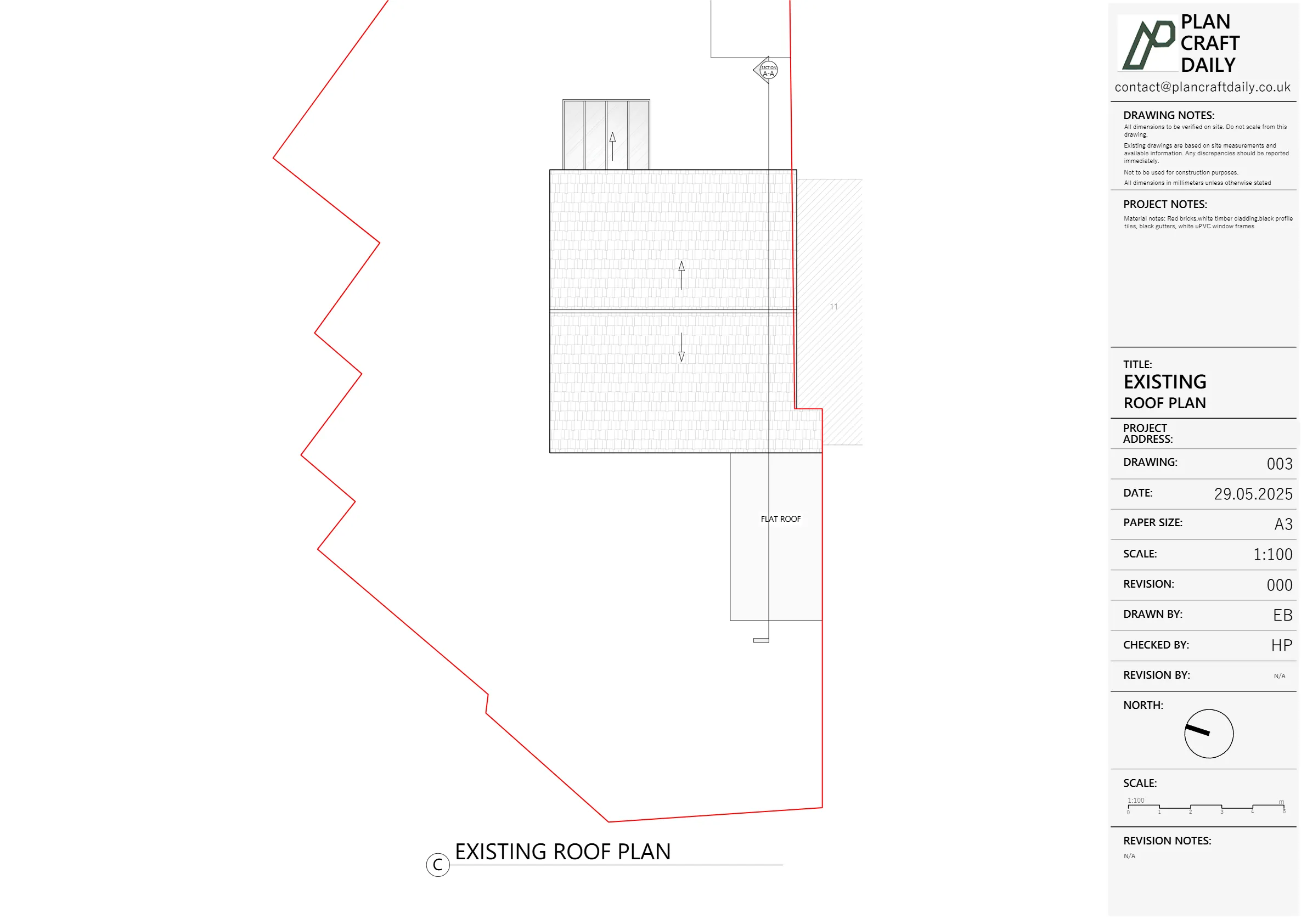
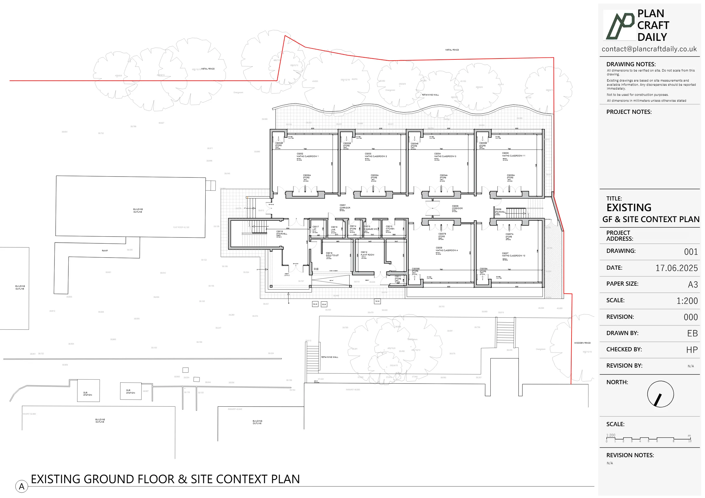
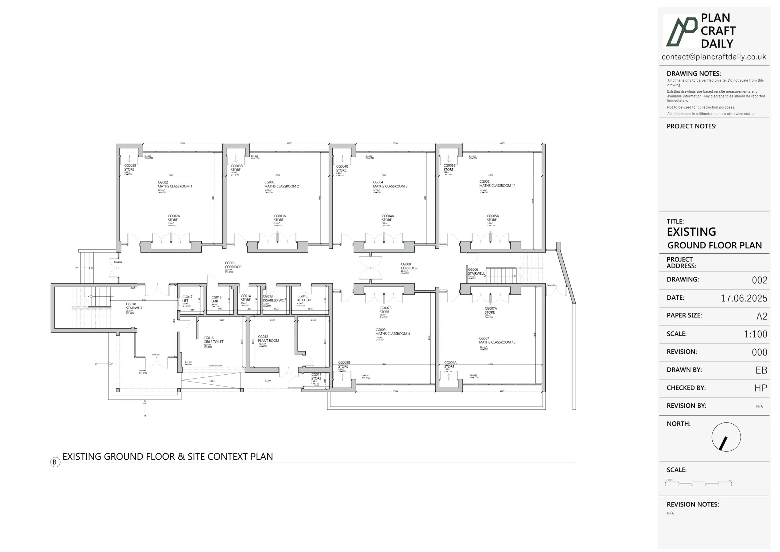
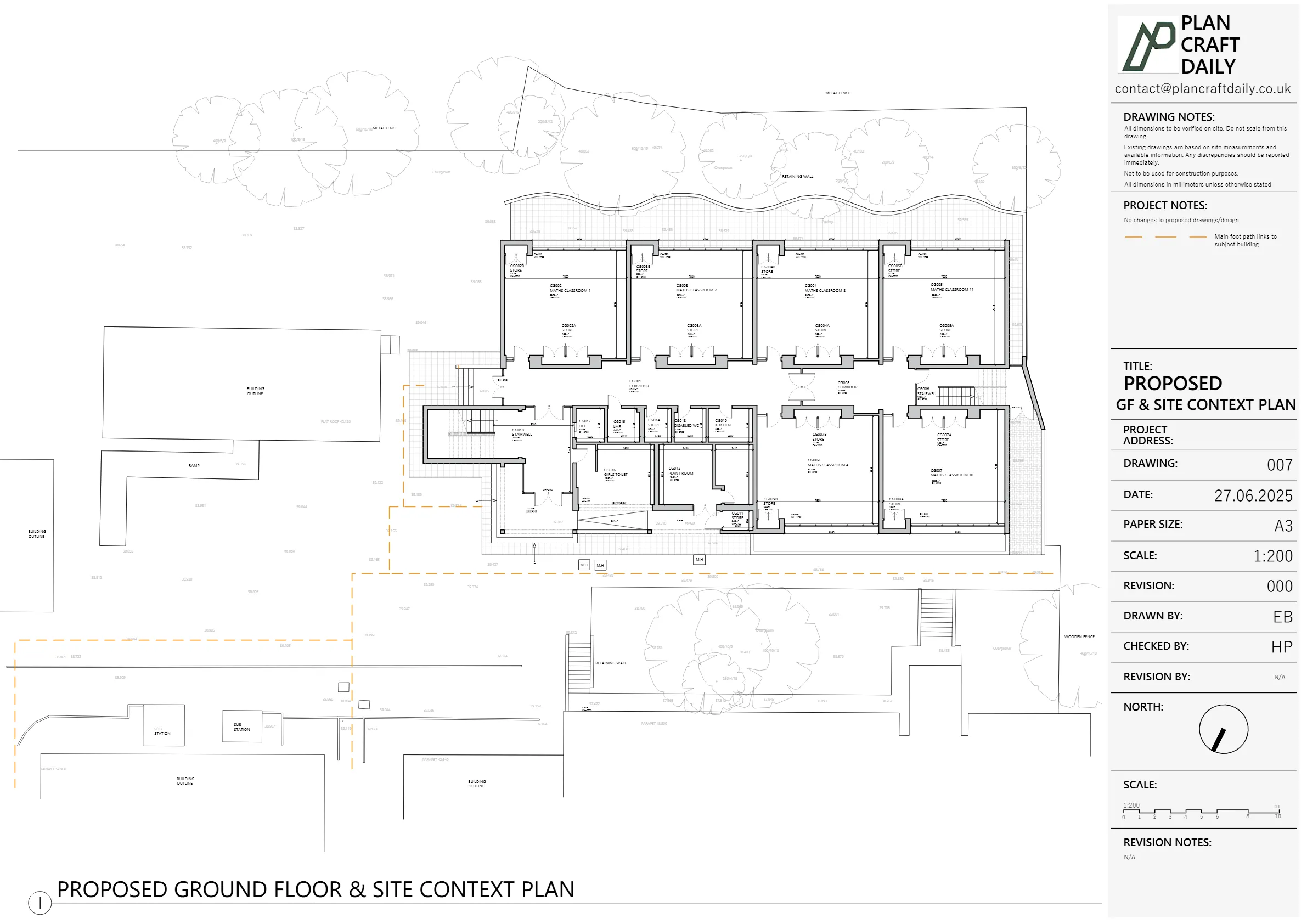
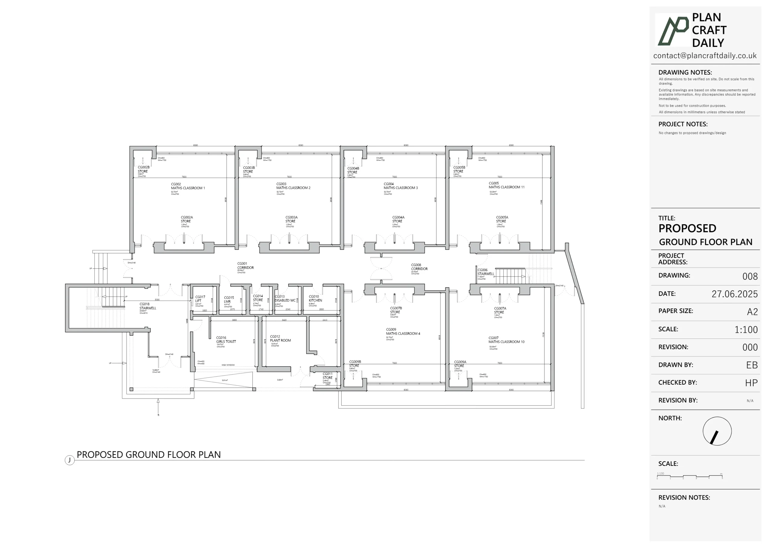
- Existing floor plans with roof plan (three plans in total).
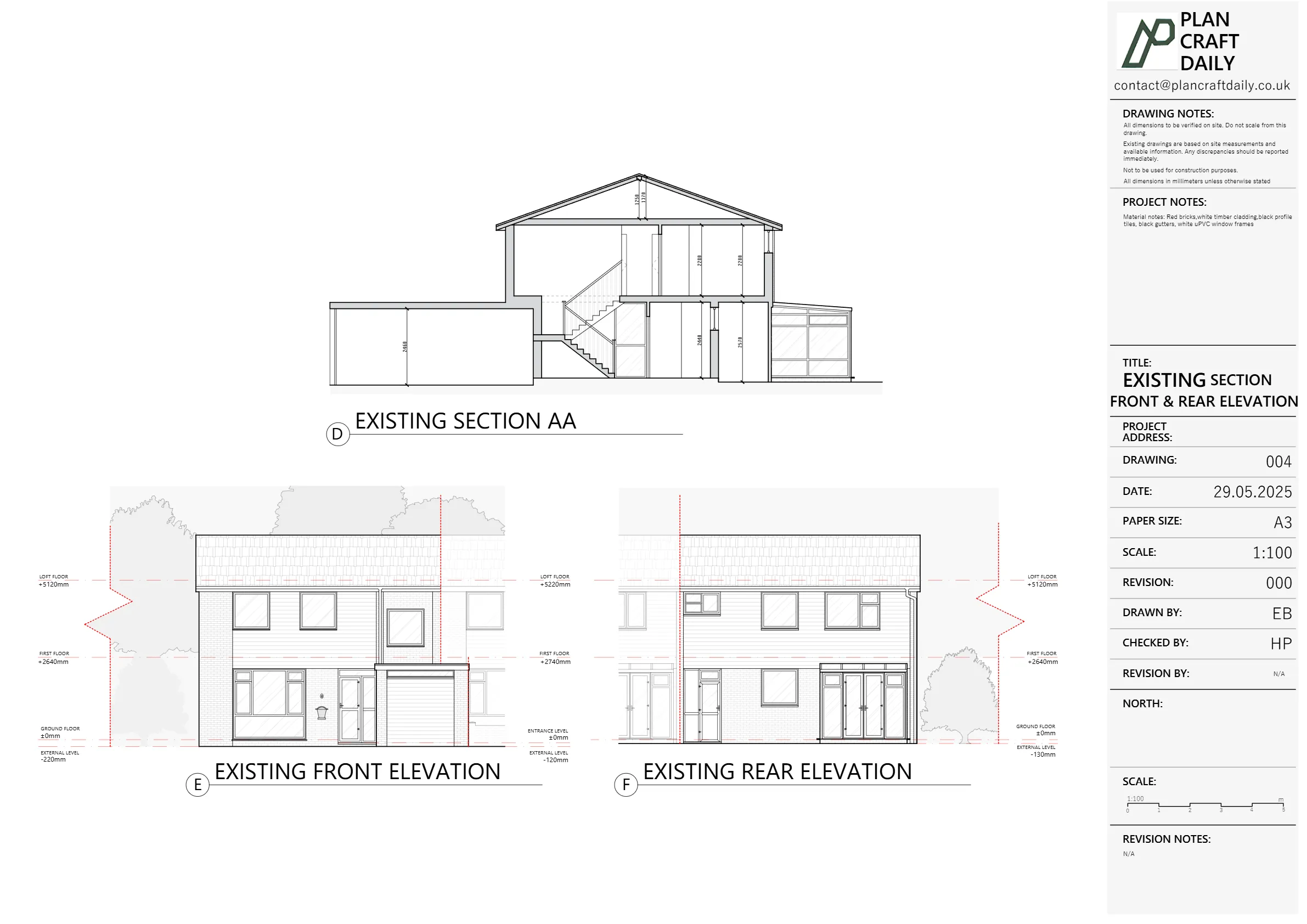
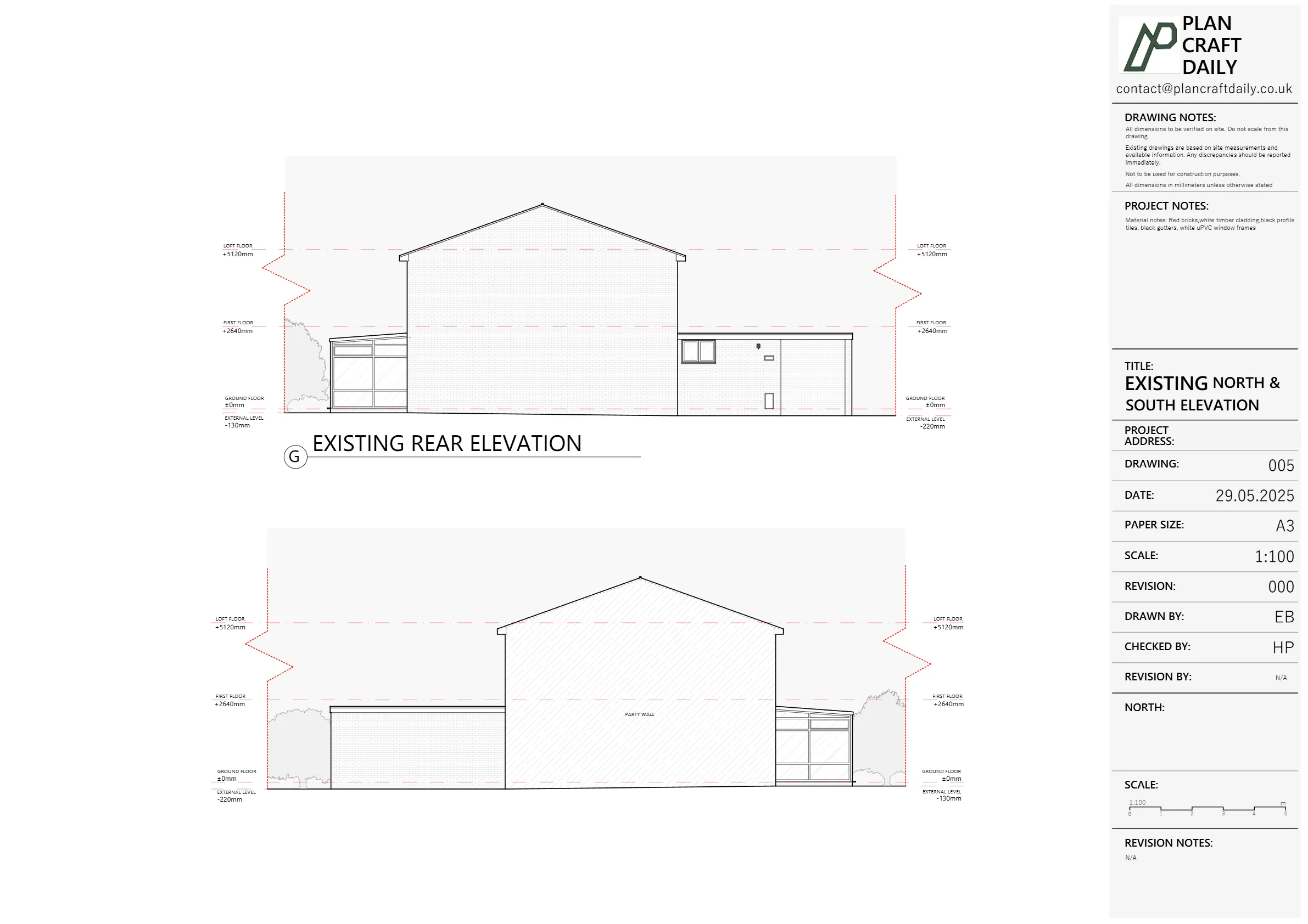
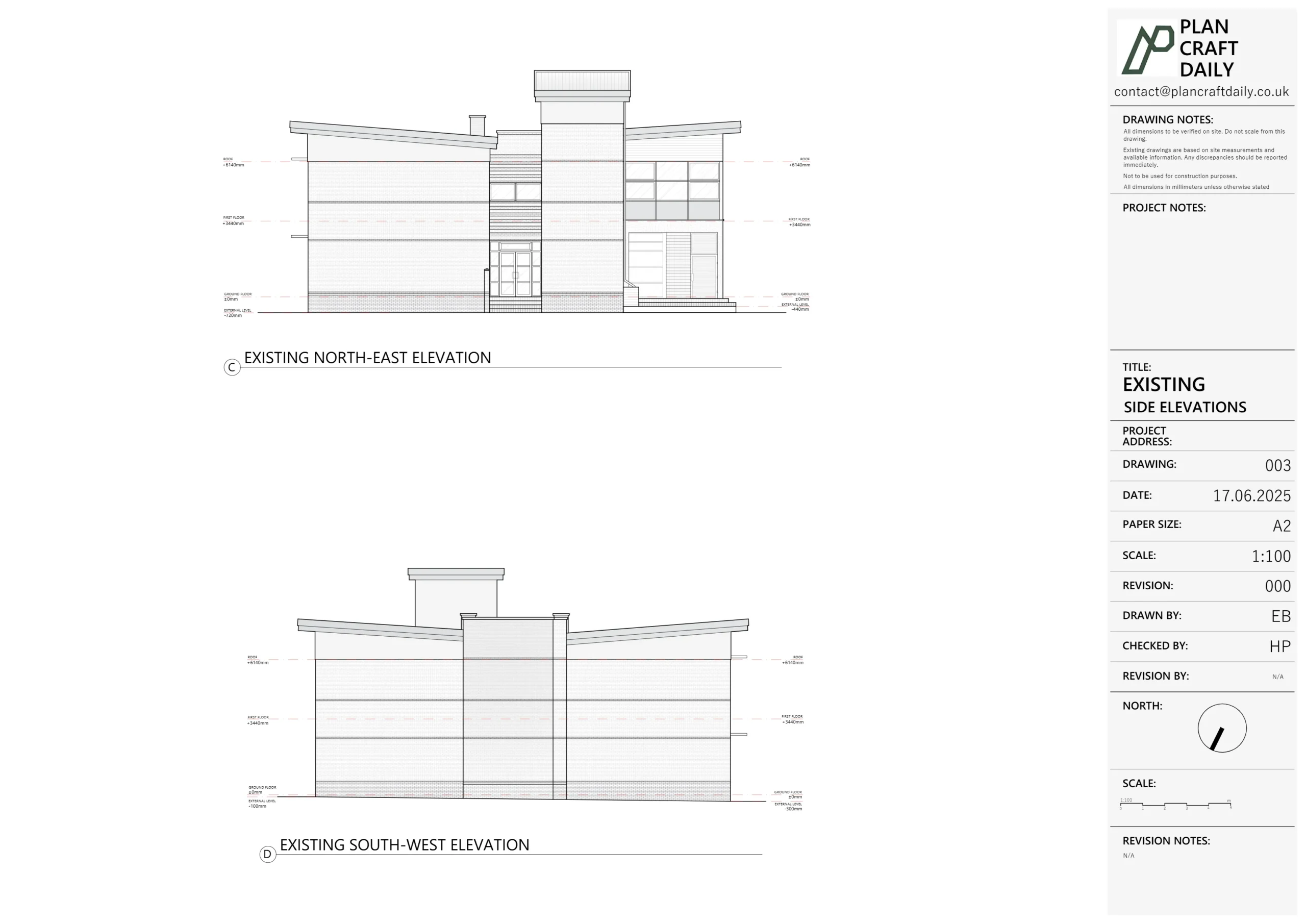
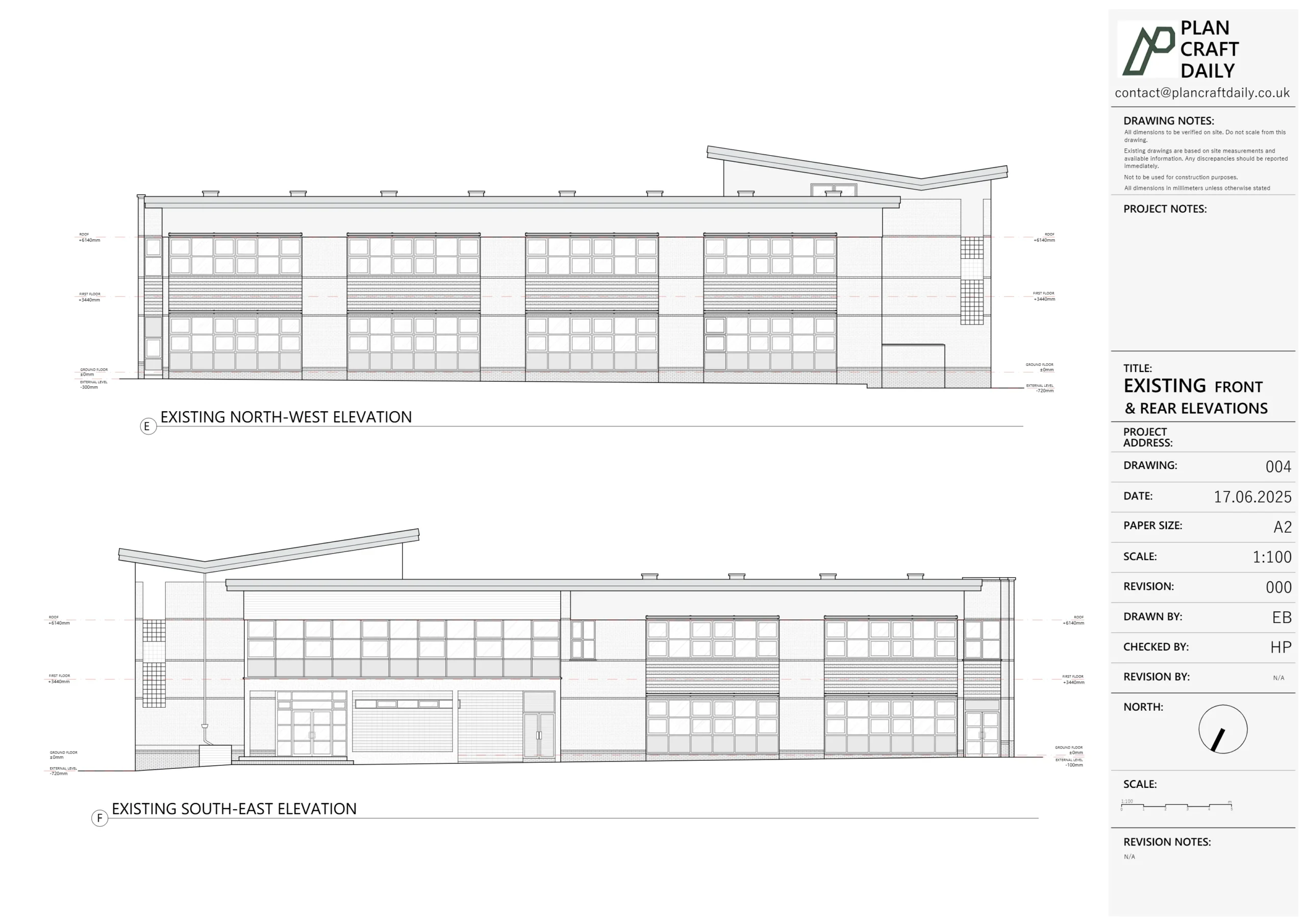
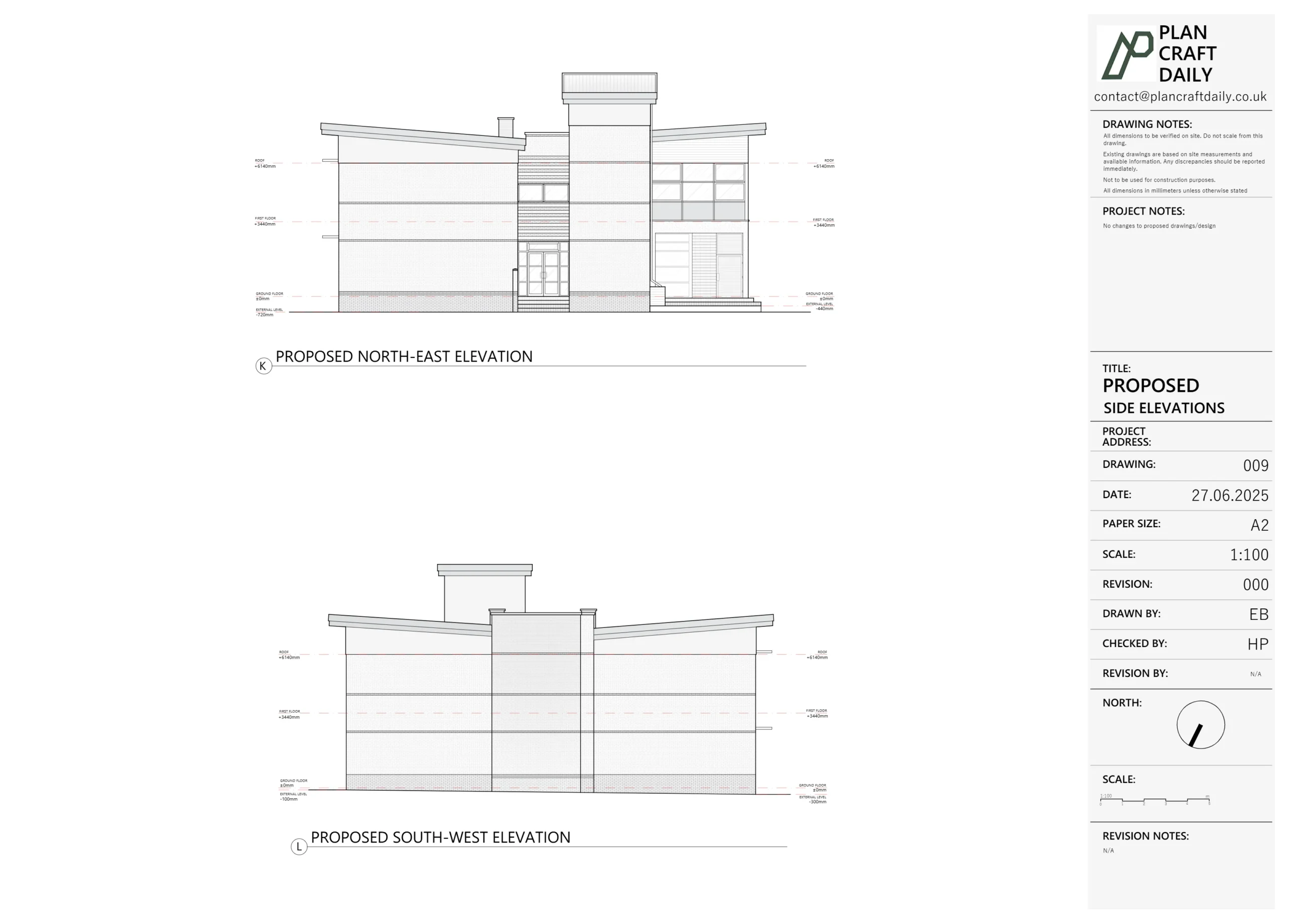
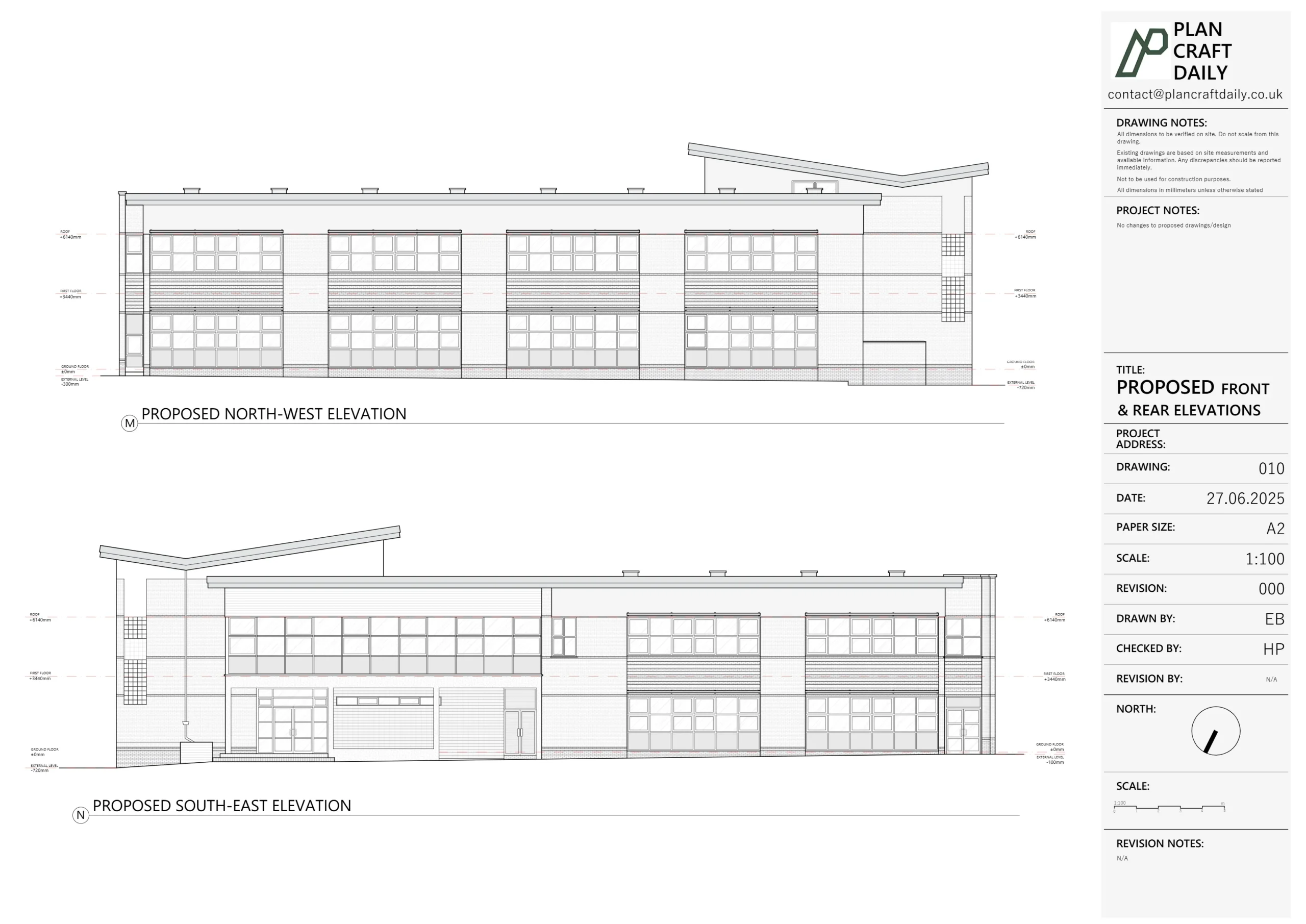
- Front, side and rear elevations.
- One key section through the most structurally relevant part of the house.
Workflow-wise, we:
- Set out the shell
Using control dimensions and the 3D scan, we established external walls, floor-to-floor heights, roof geometry and main structural lines. - Layered in internal walls and openings
All internal partitions, doorways, and openings were drawn from the scan and verified against hand measurements. Particular attention was paid to wall thicknesses, nibs and alignment between ground and first floor, as these are classic indicators of potential load-bearing elements. - Added drainage and services notes where relevant
For this job, drainage mapping was more critical on the Strathville project, but we still noted visible services and features at Leaf Close so Ells had a complete picture.
We then issued a draft drawings pack to Ells along with the final invoice, noting that once payment was settled we would issue:
- The final CAD (DWG)
- PDFs of the drawings
- The photo bundle
After Ells’s team reviewed and confirmed, payment was made and we issued the final deliverables. The card was moved to Completed in our system.
The load-bearing query – when GF and FF didn’t quite line up
A few weeks later, Ells came back to us while actively developing planning drawings for Leaf Close.
They had:
- Dropped our existing DWGs into their own templates.
- Started working up options that involved reducing or removing a section of ground-floor wall (marked “green” in their screenshot).
- Noticed that ground floor (GF) and first floor (FF) walls and site lines didn’t appear to align as expected in their working file.
Ells wrote to Harry:
“We have issued a set of drawings and are working towards planning, but I have only just noticed that the GF and FF seem to be quite off. It’s important as we are trying to work out what is load bearing etc. Just want to check that this is right?
In short I can’t get any of the walls / site lines to line through.”
Because this directly affected structural decisions, we immediately:
- Moved the Trello card from “Completed” back to “Revise”
- Treated it as a priority technical check, not a minor cosmetic change
How we handled the revision and structural alignment check
Our job here wasn’t to design the structure or certify load-bearing status – that’s ultimately for the architect and structural engineer – but we did need to be absolutely sure the measured base was sound.
We approached it in four steps:
1. Re-opening the 3D scan and survey notes
We went back to:
- The original 3D scan data for Leaf Close.
- The surveyor’s field sketches and control dimensions.
- The photo set, focusing on areas where walls stacked between floors and where beams or nibs were visible.
2. Checking GF/FF alignment in CAD
Within the CAD file we:
- Overlaid GF and FF plans precisely using the same reference point.
- Checked external wall lines first (as these should generally align unless there are overhangs/extensions).
- Then compared internal wall positions, particularly in the area Ells had highlighted in green.
In many older terrace houses, you’ll often see:
- Ground-floor structural walls that don’t have a full-width wall directly above, but carry joists or partial walls.
- Slight offsets where stair enclosures, chimney breasts or historical alterations have been made.
We verified whether apparent offsets were:
- Survey error, or
- A reflection of real-world conditions (e.g., thicker GF walls, nibs where beams land, or historic alterations).
3. Making targeted corrections (if needed)
Where our re-check showed any small inconsistencies:
- We snapped wall centres and faces back to the verified control line from the scan.
- Adjusted dimension strings to reflect the most reliable measured values.
- Ensured sections and elevations still aligned with the updated internal geometry.
The goal was to give Ells a plan where:
- Ground and first floor relationships were as true to site as possible, and
- Any misalignment that remained was genuine building behaviour, not drafting noise.
4. Explaining what the drawings could (and couldn’t) tell you about load-bearing
We then responded to Ells with:
- Confirmation of what we’d checked and, where applicable, that plans had been refined to reflect the 3D scan more tightly.
- A simple explanation that while aligned GF/FF walls often suggest load-bearing, final decisions should still be made with a structural engineer using our drawings, site inspection and, if necessary, opening-up works.
- A re-issued DWG and PDF set so their team could continue planning with confidence.
Final outcome for the architect & homeowner
By the end of the revision cycle, Ells had:
- A clean, verified set of existing drawings for Leaf Close, suitable for planning and structural design.
- Clarity on how GF and FF walls actually relate in the real building, rather than in an idealised “textbook” layout.
- Confidence that any decision to reduce or remove the green-highlighted ground-floor wall would be based on sound measured information, not guessed geometry.
- Evidence for their client that, even after “completion”, their survey and drawings provider (us) was willing to re-open and interrogate the file when a genuine technical concern was raised.
For us, Leaf Close is a good example of:
- Why we invest in 3D scanning and robust on-site note-taking.
- The value of aftercare – being ready to check and refine drawings when an architect spots something that doesn’t feel right.
- How we like to work with repeat studio clients: fast quotes, senior surveys, clear deliverables, and honest responses when structural questions arise.
If you’re planning an internal reconfiguration or considering removing walls in a London or Surrey home, this is exactly the kind of measured survey and “structurally-aware” existing drawing package we can provide – with the same willingness to dig back in if something needs a second look.
Project Details
| Service Type | Measured Survey, Existing Drawings, Internal Reconfiguration Support, 3D Scan |
| Time Taken | 1–2 weeks |
| Location | Cul-de-sac near Thames Ditton |