Key Takeaways
| Aspect | Details |
|---|---|
| Definition | Architectural drafting is the technical drawing of building plans and designs |
| Purpose | Communicates design intent, secures approvals, guides construction |
| Types | Floor plans, elevations, sections, site plans, detail drawings |
| Tools | Traditional (drafting boards, scales) and digital (CAD, BIM software) |
| Skills Needed | Technical knowledge, spatial awareness, attention to detail |
| UK Standards | Compliance with BS EN ISO 19650, RIBA Plan of Work |
| Planning Requirements | Different drawing sets required for various application types |
| Professional Help | Specialized drafting services improve approval rates and build quality |
Introduction to Architectural Drafting
Architectural drafting forms the backbone of every successful building project. You might not realize it, but those lines and symbols on paper or screen translate directly into the walls and spaces we live and work in every day. Without proper drafting, buildings simply wouldn’t get built right.
But what exactly is architectural drafting? It’s the technical process of creating detailed drawings that communicate a building’s design, specifications, and construction requirements. These drawings serve as the visual language between designers, planners, builders, and clients. In the UK, architectural drafting follows specific standards and conventions that ensure consistency and clarity across the industry.
The evolution of drafting has been pretty remarkable. Once upon a time, drafters spent hours hunched over drawing boards with T-squares, compasses, and mechanical pencils. Today, most drafting happens digitally using Computer-Aided Design (CAD) software and Building Information Modeling (BIM) systems. Despite these technological advances, the fundamental principles remain the same – accuracy, clarity, and attention to detail are still essential.
For UK projects, architectural drafting must comply with British Standards like BS EN ISO 19650 and align with the RIBA Plan of Work stages. While the technical aspects can seem overwhelming at first, understanding the basics can help anyone involved in a building project communicate more effectively with design professionals.
Fundamentals of Architectural Drafting
Getting to grips with architectural drafting means understanding its basic principles and standards. Every line, symbol, and notation serves a specific purpose and follows established conventions that architects, builders, and planning officials all recognize.
The core principles of good architectural drafting include:
- Accuracy – Measurements must be precise to ensure buildability
- Clarity – Information should be easy to read and interpret
- Consistency – Standard symbols and conventions create universal understanding
- Completeness – All necessary information must be included
- Scale – Drawings must accurately represent real-world dimensions
In the UK, drafting standards typically follow metric measurements, and drawings are created at standardized scales like 1:50 for floor plans and 1:100 for site plans. These standards help ensure that everyone involved in a project can understand and work from the same information.

The tools used in architectural drafting have changed dramatically, but they still serve the same purpose – to create precise, detailed drawings that communicate design intent. Traditional drafting tools include:
- Drafting boards and tables
- T-squares and set squares
- Scales and rulers
- Compasses and dividers
- Technical pens and pencils
Modern digital drafting tools include:
- 2D CAD software (AutoCAD, Microstation)
- 3D modeling programs (Revit, ArchiCAD)
- BIM platforms (integrating multiple design aspects)
- Rendering software (for visualization)
- Tablet drawing devices
I’ve seen many projects where poor drafting led to costly mistakes. One residential extension I worked on had incorrect dimensions on the drawings, resulting in ordered windows that were 15cm too wide for the openings. The builder had followed the drawings exactly, but the drafter had made a simple measurement error. This mistake cost the client nearly £3,000 in additional materials and labor. Proper drafting isn’t just about pretty pictures – it’s about creating accurate instructions for construction.
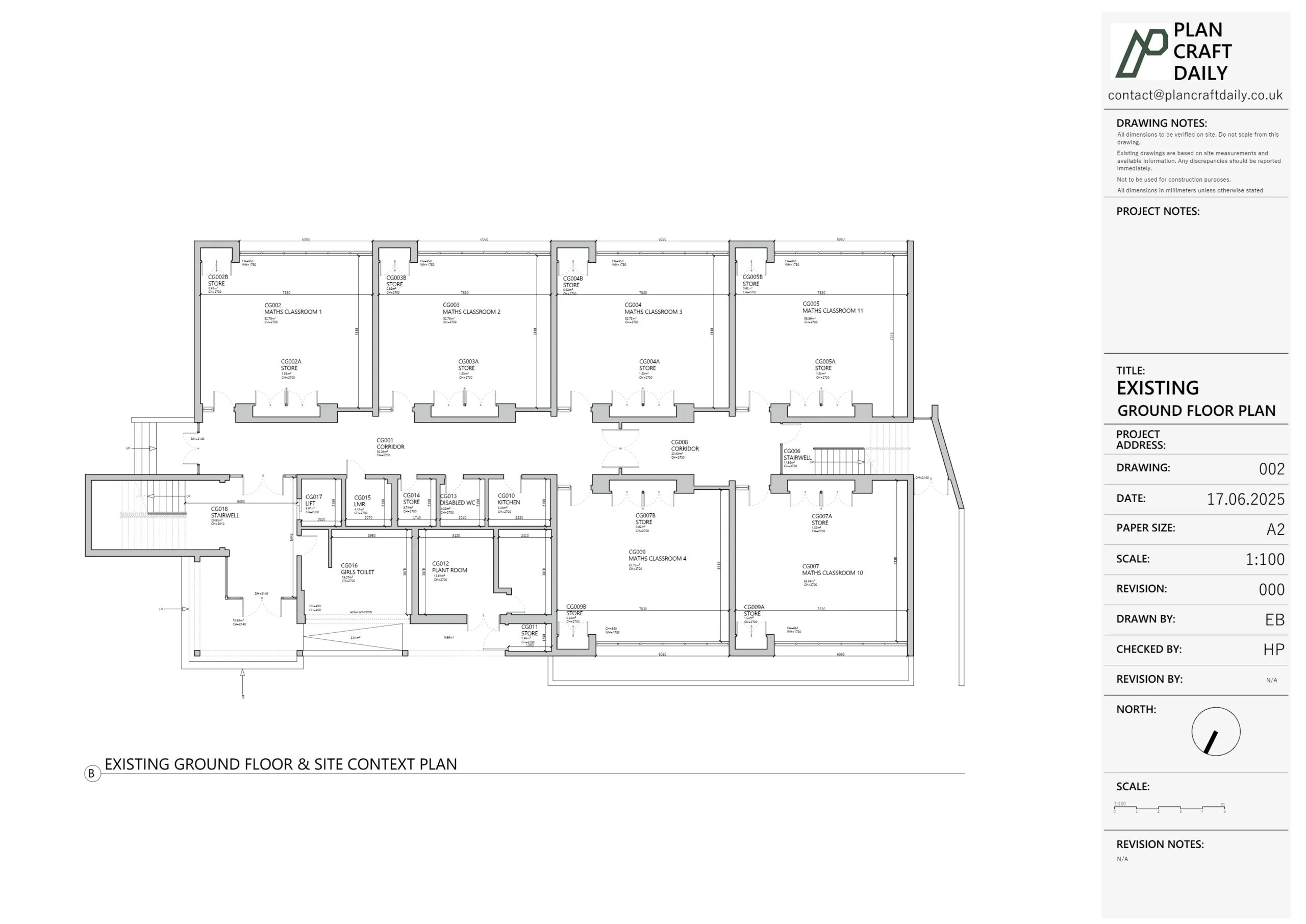
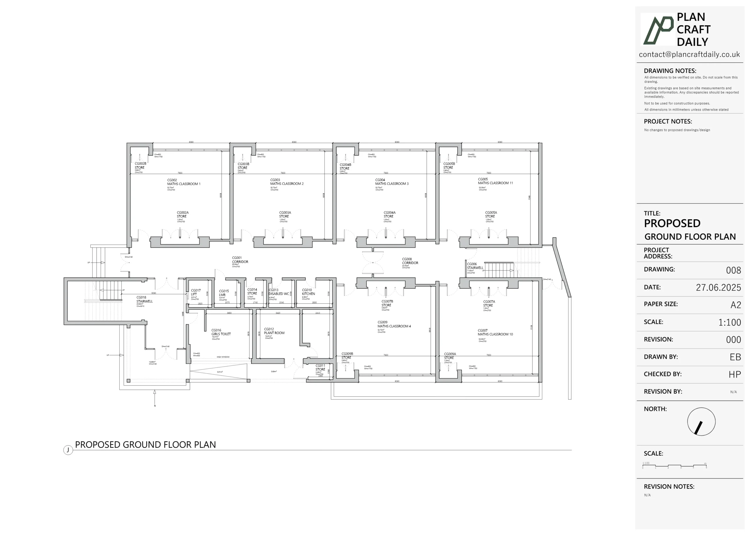
Understanding Floor Plans
Floor plans are perhaps the most recognizable type of architectural drawing. They show the layout of a building as if you were looking down from above with the roof removed. Good floor plans communicate not just room sizes but how spaces relate to each other, where doors and windows are located, and how people will move through the building.

The essential components of a floor plan include:
- Walls – Shown as parallel lines with appropriate thickness
- Doors – Including swing direction and door type
- Windows – With proper dimensions and type
- Stairs – Showing direction of travel and number of steps
- Fixed fixtures – Like kitchen units, bathroom fixtures, built-in furniture
- Dimensions – Typically shown in millimeters in UK drawings
- Room names and areas – Identifying spaces and their sizes
- Orientation – Usually with a north arrow
- Scale – Often 1:50 or 1:100 for residential projects
Reading floor plans takes a bit of practice, but once you understand the symbols and conventions, they become much easier to interpret. Wall thicknesses indicate construction type – thicker for external walls, thinner for internal partitions. Dashed lines typically show overhead features or items below, while solid lines represent walls and fixed elements.
Common symbols in UK floor plans include:
| Symbol | Meaning |
|---|---|
| Single line with arc | Hinged door and swing direction |
| Rectangle in wall | Window |
| Circle with cross | Ceiling light fixture |
| Small square | Electrical outlet |
| Parallel lines with small lines crossing them | Stairs (small lines are the steps) |
I remember working with a family who couldn’t visualize their home from the floor plans alone. We created a simple 3D model based on the floor plans, and suddenly everything clicked for them. They could see how the kitchen would connect to the dining area and how light would flow through the space. Floor plans might seem technical, but they’re telling the story of how you’ll live in your new space.
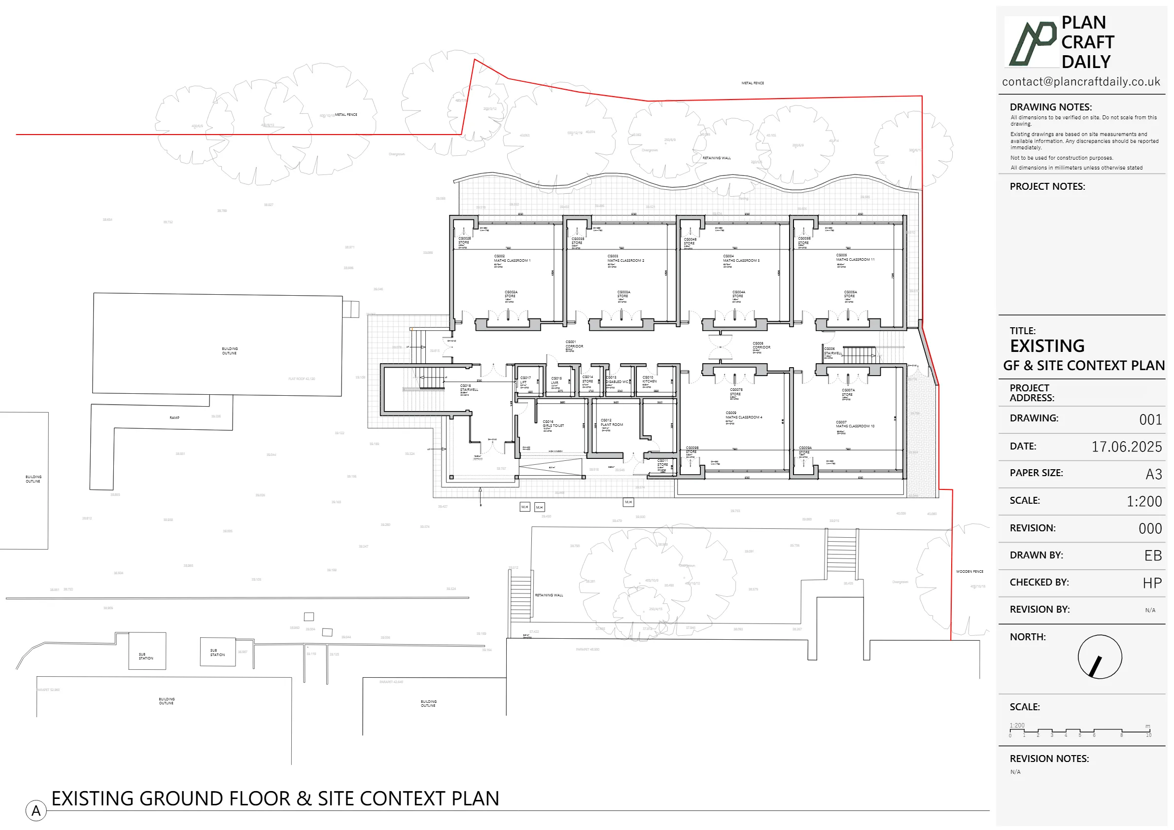
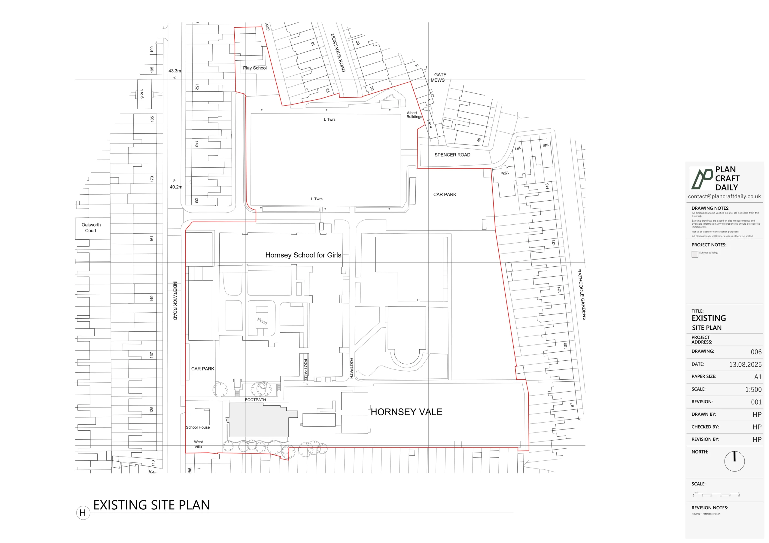
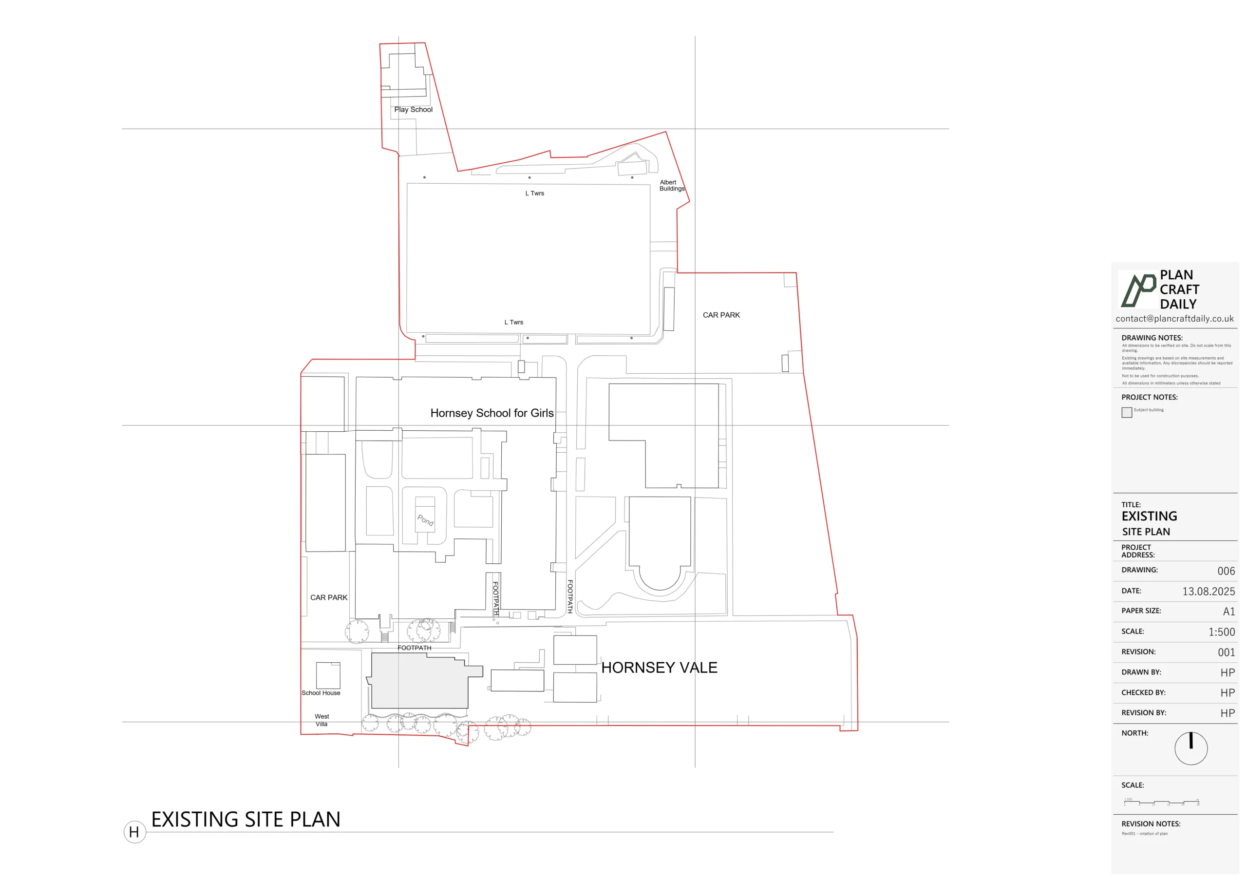
Creating Existing Design Documentation
Before any changes can be made to a building, we need accurate documentation of its current state. Existing design drawings provide the foundation for all renovation, extension, and conversion projects. These drawings capture the building as it stands today, including all its quirks, features, and dimensions.

Creating accurate existing drawings involves several key steps:
- Initial research – Gathering any available previous drawings or documentation
- Site visit – Physically examining the property
- Measured survey – Taking precise measurements of all building elements
- Photography – Documenting visual features and conditions
- Drawing production – Creating accurate plans, elevations, and sections
The level of detail required in existing drawings depends on the project scope. For a simple internal renovation, floor plans and key elevations might suffice. For a major renovation or listed building, much more detailed documentation is needed, potentially including:
- Detailed molding profiles
- Ceiling details
- Floor construction
- Window and door schedules
- Material specifications
- Structural elements
You’d be amazed how many old buildings don’t match their original plans. I once surveyed a Victorian terraced house where a previous owner had moved an entire staircase without updating any drawings. The current owners had bought the property with old plans that showed a completely different layout! Without an accurate survey and existing drawings, their planned extension would have been a disaster.
Another common issue is discovering hidden features during renovation – removed fireplaces, blocked doorways, or altered structural elements that don’t appear on old drawings. Proper existing documentation helps identify these potential surprises before construction begins, saving time and money.
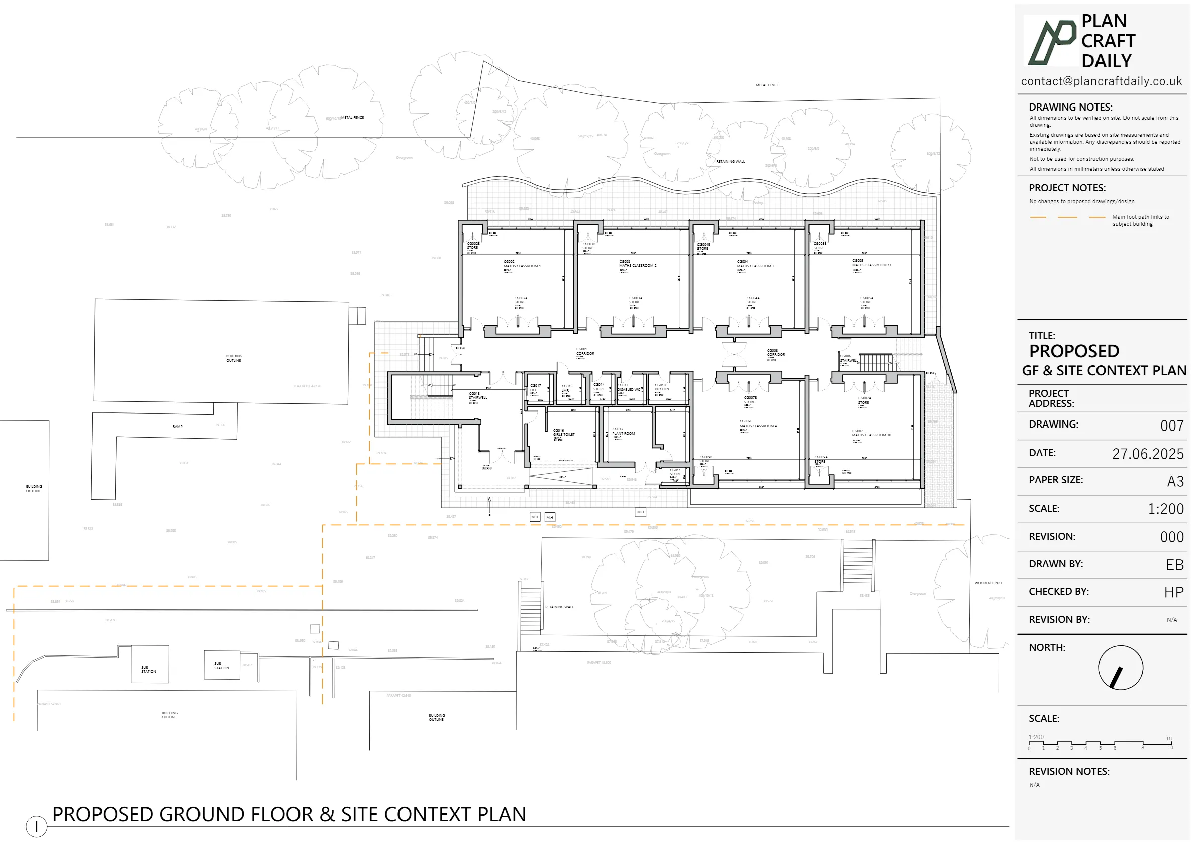
Developing Proposed Designs
Once the existing conditions are documented, the exciting part begins – creating proposed design drawings that show what the building will become. These drawings translate ideas and requirements into concrete plans for approval and construction.

The proposed design process typically follows these stages:
- Concept development – Initial ideas based on client needs
- Schematic design – Basic spatial arrangements and layouts
- Design development – Refinement of concepts with more detail
- Construction drawings – Detailed plans for building approval and construction
Good proposed drawings clearly distinguish between existing elements to be retained and new construction. This is typically done through different line weights, hatching patterns, or color coding. In UK planning submissions, it’s common practice to show:
- Existing walls to be demolished (often dashed)
- New construction (often darker or solid lines)
- Areas to be altered (with specific notations)
Proposed drawings must include sufficient detail for both planning approval and construction purposes. For residential projects, this typically includes:
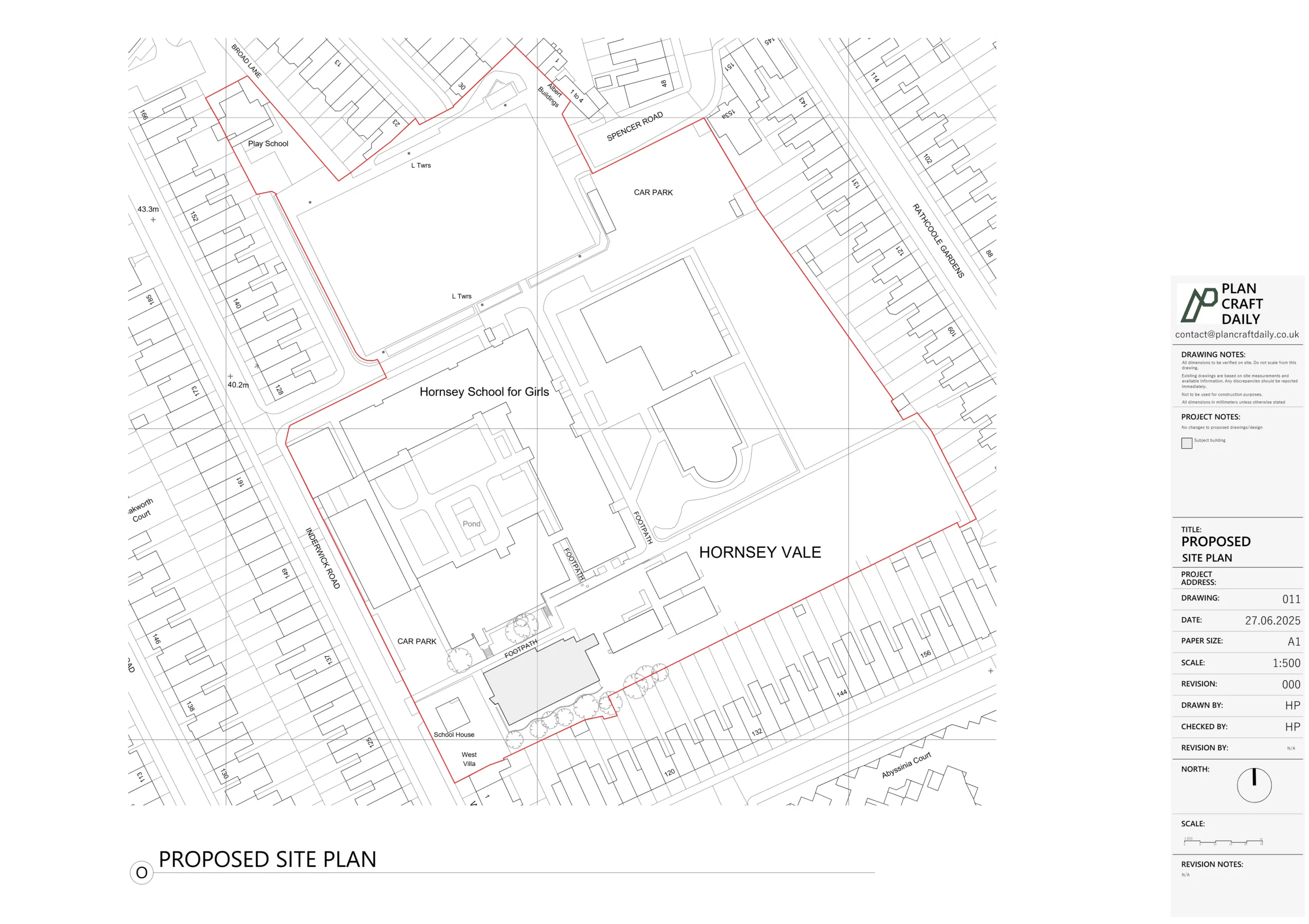
- Site plan showing the property boundaries and building position
- Floor plans for each level
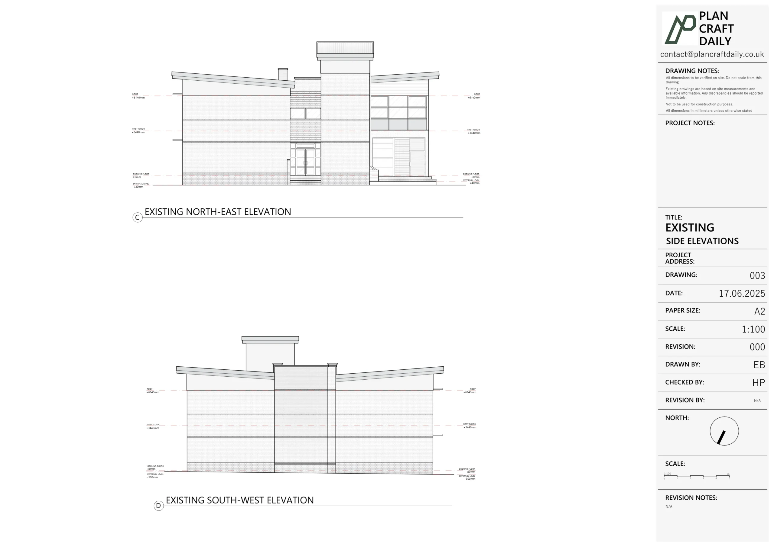
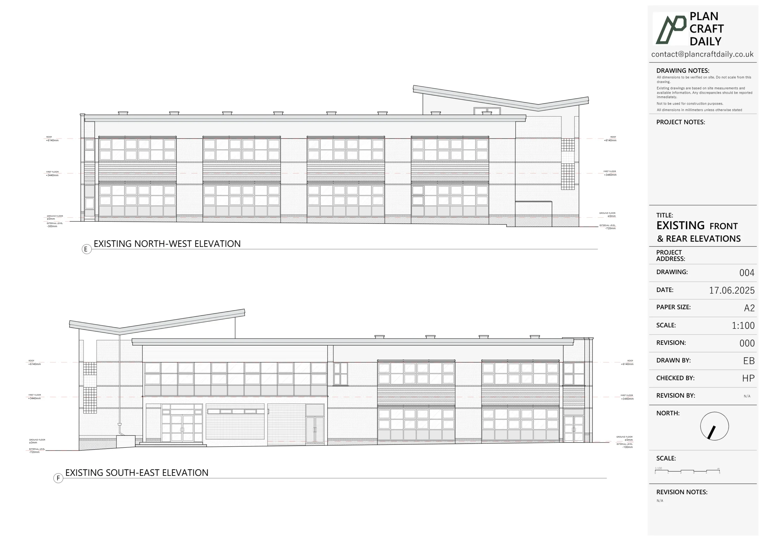
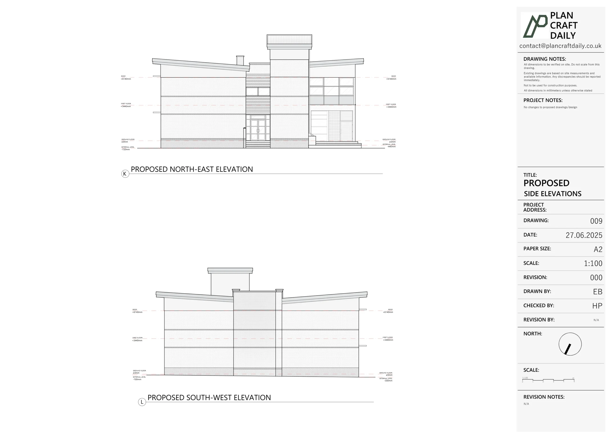
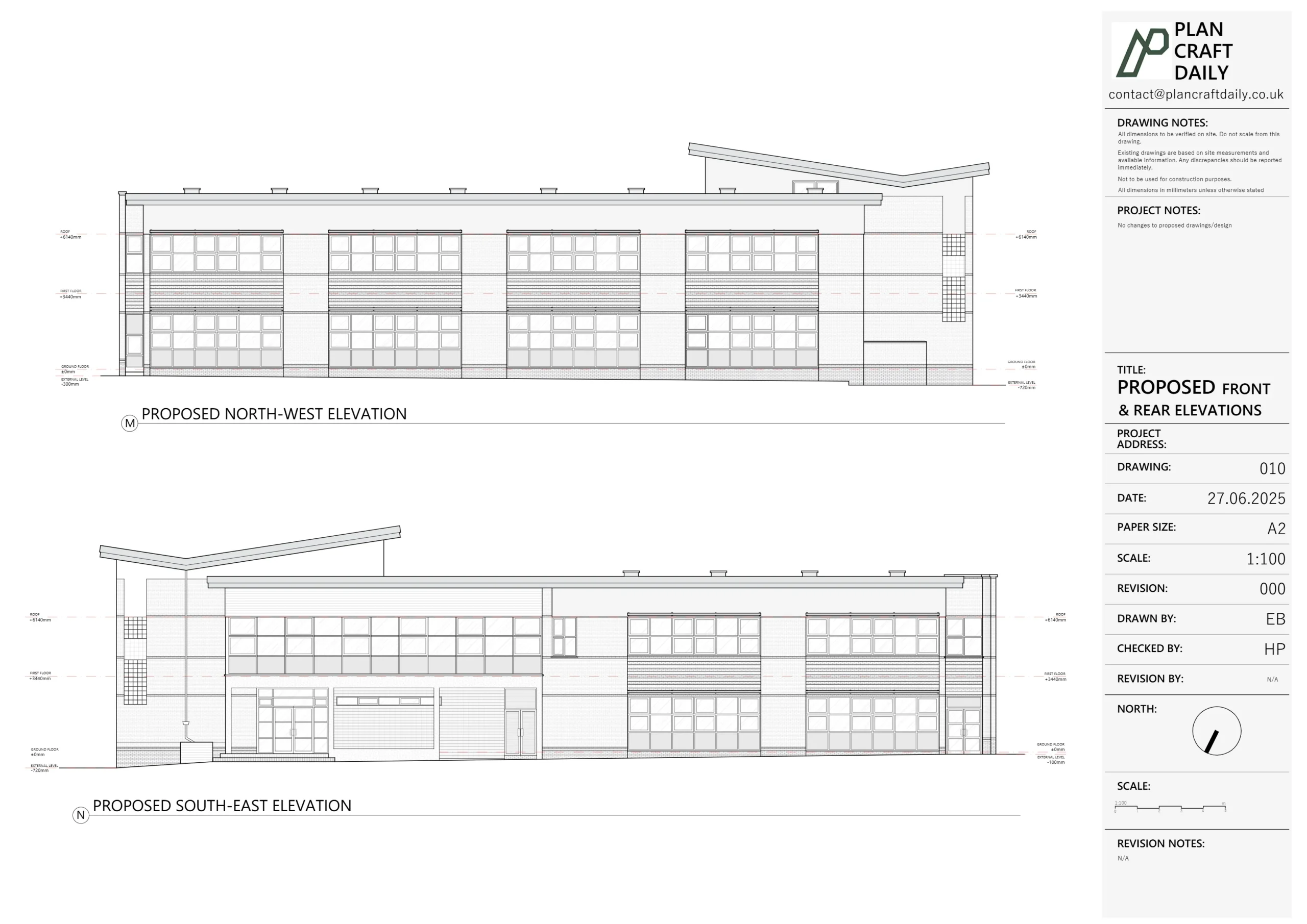
- External elevations from all sides
- Key sections through important parts of the building
- Detailed drawings of specific features
- Materials specifications
I’ve found that the most successful proposed drawings balance technical accuracy with clarity. One particularly effective technique is using the “existing vs. proposed” side-by-side format, where identical views of current and future states make changes immediately obvious. This approach helps clients understand exactly what will change and makes planning applications more straightforward.
Measured Surveys and Technical Requirements
The foundation of any good architectural drawing is accurate measurement. Measured surveys provide the precise dimensions and spatial information needed to create reliable drawings for both existing and proposed designs.

Traditional measured surveys involve manual measurement using:
- Tape measures
- Laser distance meters
- Spirit levels
- Plumb lines
- Hand tools for detail measurement
Modern technology has transformed this process with:
- 3D laser scanning
- Photogrammetry
- Digital measuring devices
- Mobile apps for on-site recording
- Drones for external and roof surveys
The level of accuracy required depends on the project. For listed buildings or precise restoration work, measurements might need to be accurate to within a few millimeters. For standard residential work, accuracy within 10-20mm is typically sufficient. The Royal Institution of Chartered Surveyors provides guidance on appropriate survey accuracy for different project types.
A comprehensive measured survey should capture:
- Overall building dimensions (length, width, height)
- Room dimensions
- Wall thicknesses
- Door and window positions and sizes
- Floor levels and ceiling heights
- Position of structural elements
- Location of services
- External features and site boundaries
I’ve seen countless projects where poor initial surveys led to serious problems. On one project, an inaccurate survey missed the fact that a load-bearing wall wasn’t perfectly vertical – it leaned about 5 degrees. When new kitchen units were designed based on the incorrect drawings, they didn’t fit the space properly, requiring expensive on-site modifications.
For complex projects, it’s worth investing in professional measured survey services. The cost is typically recouped many times over by avoiding errors during construction. At Plan Craft Daily, precise measured surveys form the foundation of our drawing services, ensuring accuracy from the very beginning of every project.
Specialized Drafting: Lease Plans
While general architectural drawings serve many purposes, some projects require specialized types of drawings. Lease plans are a perfect example – these technical documents define the boundaries of leased spaces within buildings and require specific drafting approaches.

Lease plans differ from standard architectural drawings in several important ways:
- They focus primarily on boundaries rather than design features
- They must comply with Land Registry requirements
- They often use specific color coding for different demises
- They require precise legal descriptions of spaces
- They typically include vertical boundaries (not just horizontal)
In the UK, lease plans must comply with Land Registry Practice Guide 40, which specifies:
- Plans must be drawn to a stated scale (typically 1:100, 1:200, or 1:500)
- North direction must be indicated
- The property must be clearly identified
- Boundaries must be clearly marked
- Any shared or excluded areas must be indicated
- Reference to adjoining properties should be included
Common elements in lease plans include:
- Demise boundaries (the leased area)
- Shared areas and access routes
- Structural elements
- Rights of way
- Parking spaces
- External areas
- Service locations
Creating accurate lease plans requires specialized knowledge of both drafting and property law. Many commercial property disputes arise from ambiguous lease plans, so precision is essential. I once dealt with a case where an unclear lease plan led to a year-long dispute over who was responsible for maintaining a shared staircase – an issue that could have been avoided with better drafting.
While general architectural drafting can sometimes be handled by clients themselves, lease plans should always be prepared by professionals who understand the legal implications. The cost of professional lease plan drafting is minimal compared to the potential legal expenses of boundary disputes.
Drafting for Planning Applications
One of the most common uses for architectural drafting is in planning applications. Whether you’re building a new structure, extending an existing one, or changing a building’s use, planning authorities require specific drawings to assess your proposal.

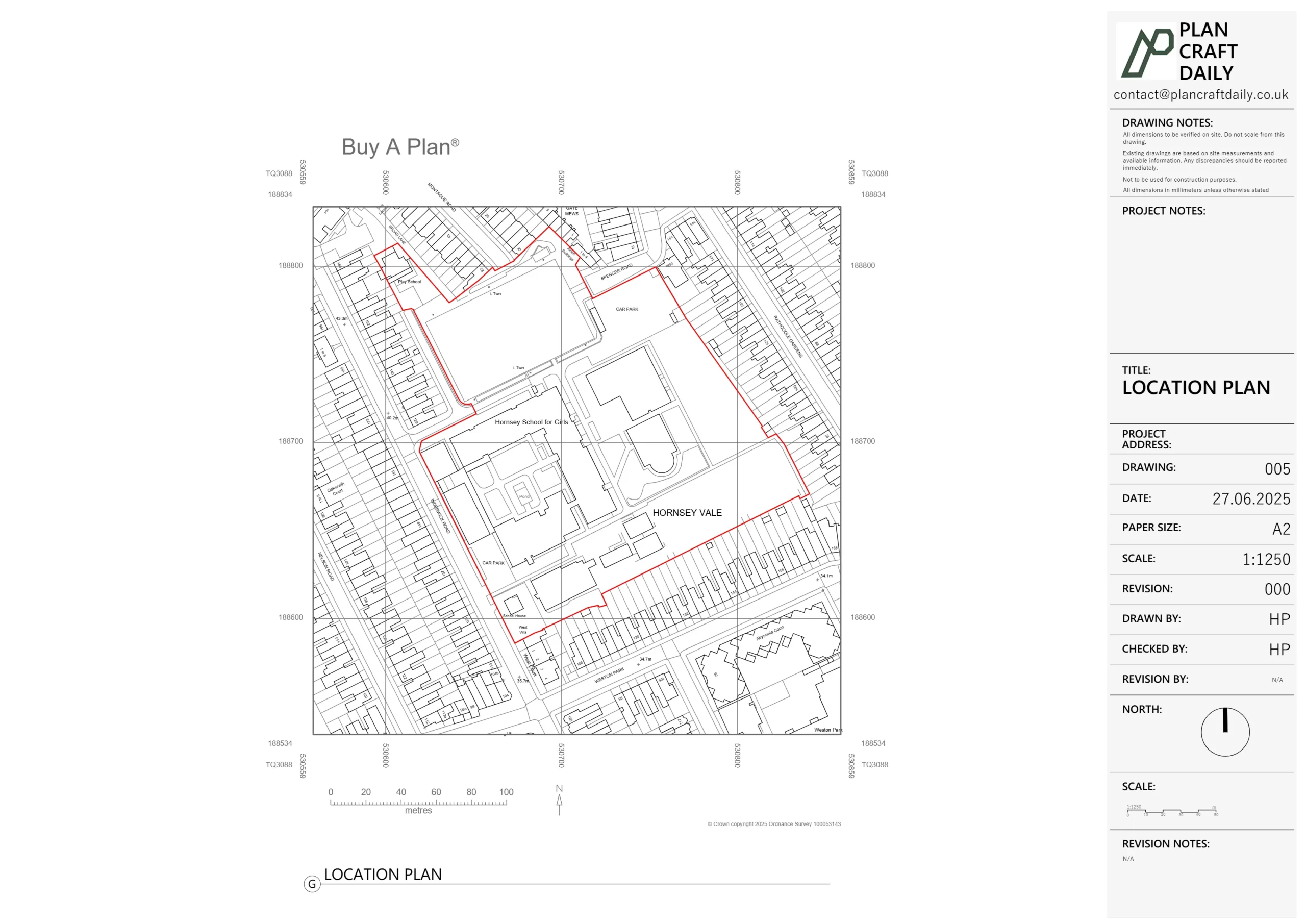
Different types of planning applications require different drawing sets. For a standard householder application in the UK, you’ll typically need:
- Location plan (1:1250 or 1:2500) – Shows the site in its wider context
- Block/site plan (1:200 or 1:500) – Shows the property boundaries and position of buildings
- Existing and proposed floor plans (1:50 or 1:100) – Shows internal layouts
- Existing and proposed elevations (1:50 or 1:100) – Shows external appearance
- Existing and proposed sections (where relevant) – Shows internal heights and construction
Planning drawings must strike a balance between providing sufficient detail for assessment while not overwhelming with unnecessary information. For planning purposes, construction details are usually not required, but clear representation of scale, massing, and appearance is essential.
Common requirements for planning drawings include:
- Clearly labeled “existing” and “proposed” drawings
- Consistent scales across drawing sets
- North arrow on all plans
- Dimensions in metric units
- Clear indication of site boundaries
- Street names and contextual information
- Materials specifications for external finishes
I’ve seen many planning applications rejected due to inadequate or incorrect drawings. One client had their extension application refused because their drawings didn’t accurately show the relationship with neighboring properties. After we redrew the plans with correct context information, the application was approved without any design changes. The drawings themselves made all the difference.
Local planning authorities may have specific requirements for drawing submissions, so it’s worth checking their validation checklists before preparing application drawings. The UK Planning Portal provides guidance on national requirements, but local authorities often have additional standards.
Drawings for planning applications should communicate design intent clearly while demonstrating compliance with planning policies. They need to be technically accurate but accessible enough for non-specialists on planning committees to understand. This balance requires skill and experience, which is why professional drawing services like those provided by Plan Craft Daily can significantly increase the chances of planning approval.
Frequently Asked Questions about Architectural Drafting
What’s the difference between architectural drawings and architectural drafting?
Architectural drawings are the finished products, while drafting is the process of creating those drawings. Architectural drafting involves the technical skills and knowledge required to produce accurate, clear, and compliant drawings. Think of it like the difference between a meal and cooking – one is the result, the other is the process of creating it.
Do I need professional drafting services for small projects?
Even small projects benefit from professional drafting. Accurate drawings help you:
- Get reliable quotes from builders
- Secure necessary approvals more easily
- Avoid costly mistakes during construction
- Create a clear record of what was built For very simple projects, you might manage with DIY drawings, but anything involving structural changes or planning permission warrants professional input.
What software is used for architectural drafting?
Common software used in the UK includes:
- AutoCAD – The industry standard for 2D drafting
- Revit – Popular for BIM and 3D modeling
- ArchiCAD – Another powerful BIM tool
- SketchUp – Used for initial 3D concepts
- Microstation – Common in larger firms and for infrastructure projects
- Vectorworks – Popular with smaller practices
How long does it take to prepare architectural drawings?
Timeframes vary depending on project complexity:
- Simple existing drawings: 1-2 weeks
- Basic planning drawings for extensions: 2-3 weeks
- Comprehensive drawing packages for new builds: 4-8 weeks
- Complex projects or listed buildings: 8+ weeks These timeframes assume all information is readily available and no major revisions are required.
How much do architectural drafting services cost?
Costs vary based on project size and complexity:
- Basic measured survey and existing drawings: £500-£1,500
- Planning drawings for simple extensions: £1,000-£2,500
- Full planning and building regulation packages: £2,500-£5,000
- Comprehensive new build packages: £5,000+ Professional drafting typically represents 3-8% of total construction costs – a worthwhile investment considering the potential cost of errors.
Can I use existing drawings instead of commissioning new ones?
While using existing drawings as a starting point can save time, they should always be verified against current conditions. Buildings change over time, and old drawings are often inaccurate. Even recent drawings should be checked for accuracy before being used as the basis for new work.
What’s the difference between planning drawings and building regulation drawings?
Planning drawings focus on appearance, size, and position to demonstrate compliance with planning policies. Building regulation drawings focus on technical construction details to demonstrate compliance with building standards. Key differences:
- Planning: external appearance, context, visual impact
- Building regs: construction methods, insulation, structure, services
Do I need CAD files or will PDFs be sufficient?
For most clients, PDF drawings are sufficient for review and sharing. However, CAD files (like DWG format) are useful if:
- You plan to make future modifications
- Your builder or contractor uses CAD software
- You need to coordinate with other technical consultants
- You want maximum flexibility for future use
Ready to Start Your Project?
Understanding architectural drafting is the first step toward a successful building project. For professional measured surveys and planning drawings tailored to your specific needs, contact Plan Craft Daily today.
Last updated: March 2025
Sources: